
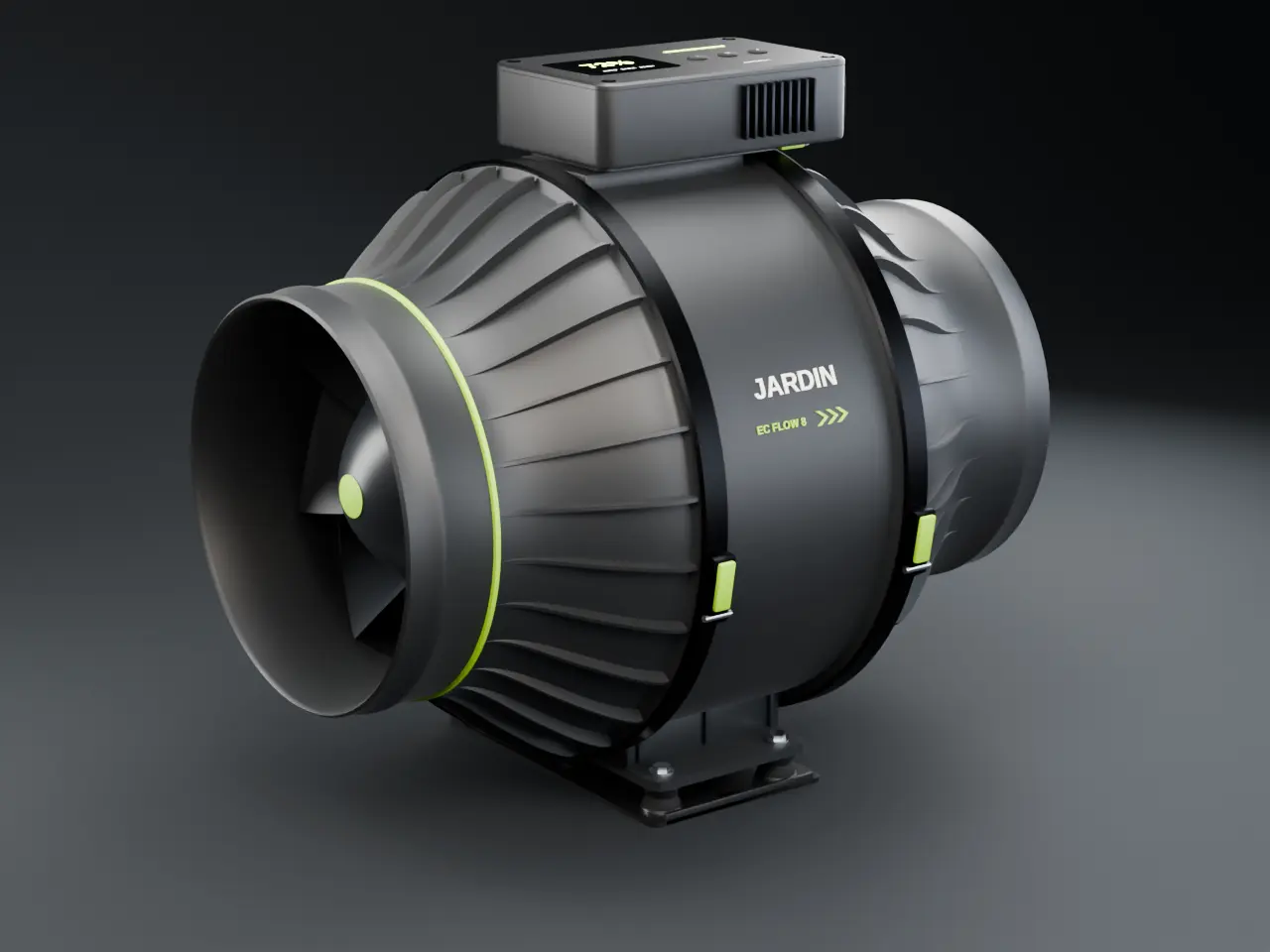
Jardin EC Flow · inline fans, filters and circulation · early access
- Engineered · ready for tooling
- Reservations on Fund the Bay
- Generation 1 · G1-r01
Quiet air you can service by hand.
Five inline EC fans from 4 to 12 inch, a carbon filter on the same collar for each, two oscillating circulation fans and a set of duct parts that all click together. Open one clamp band and the impeller and motor come out the front. The controller slides off onto your wall.
5 sizes4, 6, 8, 10 and 12 inch ducts Designed
150–1,800CFM free-air targets across the range Designed
0 toolsto open the housing and lift the motor out Designed
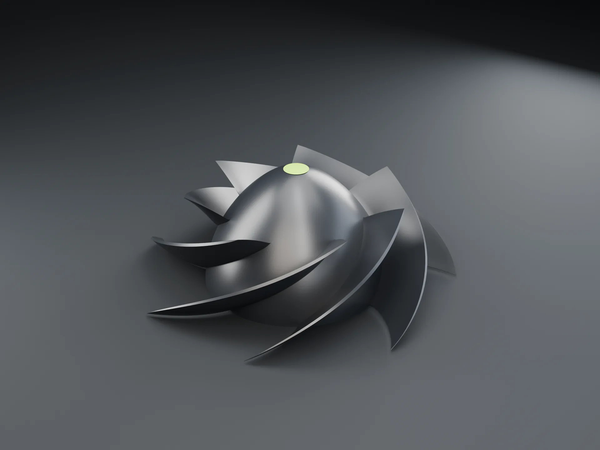
7/11 · 9/13blades and vanes, counts that share no factor Designed
1 collarper duct size, on every fan, filter and duct part Designed
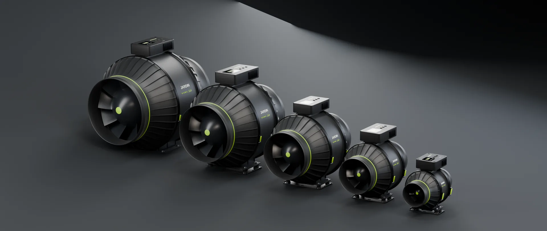 3D render · the EC Flow range
Concept renders made from the design files, not product photos. Every number on this page is a design target Designed or worked from one Modelled. Jardin has been prototyped for years; the production parts are built once tooling starts.
Watch · concept renders, narrated
See it work.
Short films made from the design files. Nothing here is a product photo; the hardware is in development after years of prototypes.
360° · every side
Turn it round.
Drag a picture to turn it, or press Spin. Each one is 24 views of the same design that is behind every other picture on this page: concept renders, not product photos.
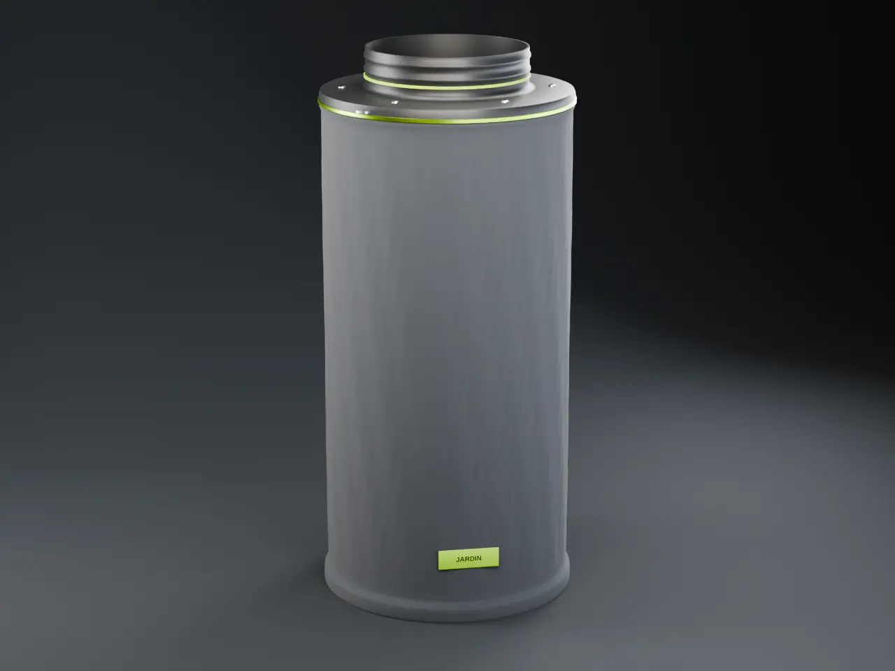
Carbon Flow 8
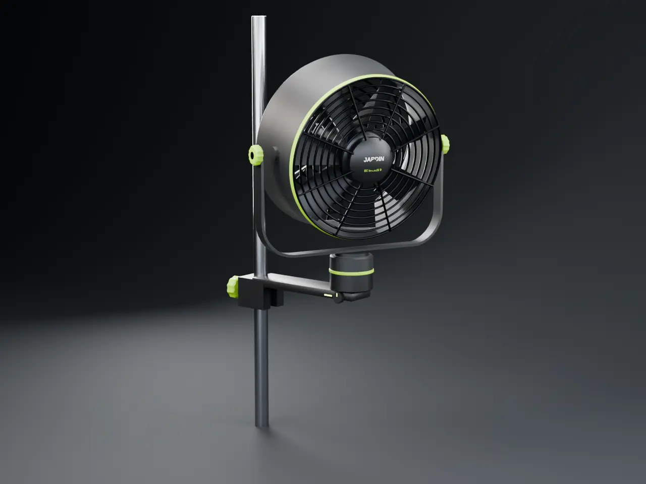
EC Breeze 9
Every size · spinning, at your speed Modelled
Five fans. Watch each one move air.
Pick a size to see it whole, then look down its throat: the impeller is drawn from the real blade and vane counts, and the air streaming out of it grows with that fan's airflow target. Drag the speed and every fan follows.
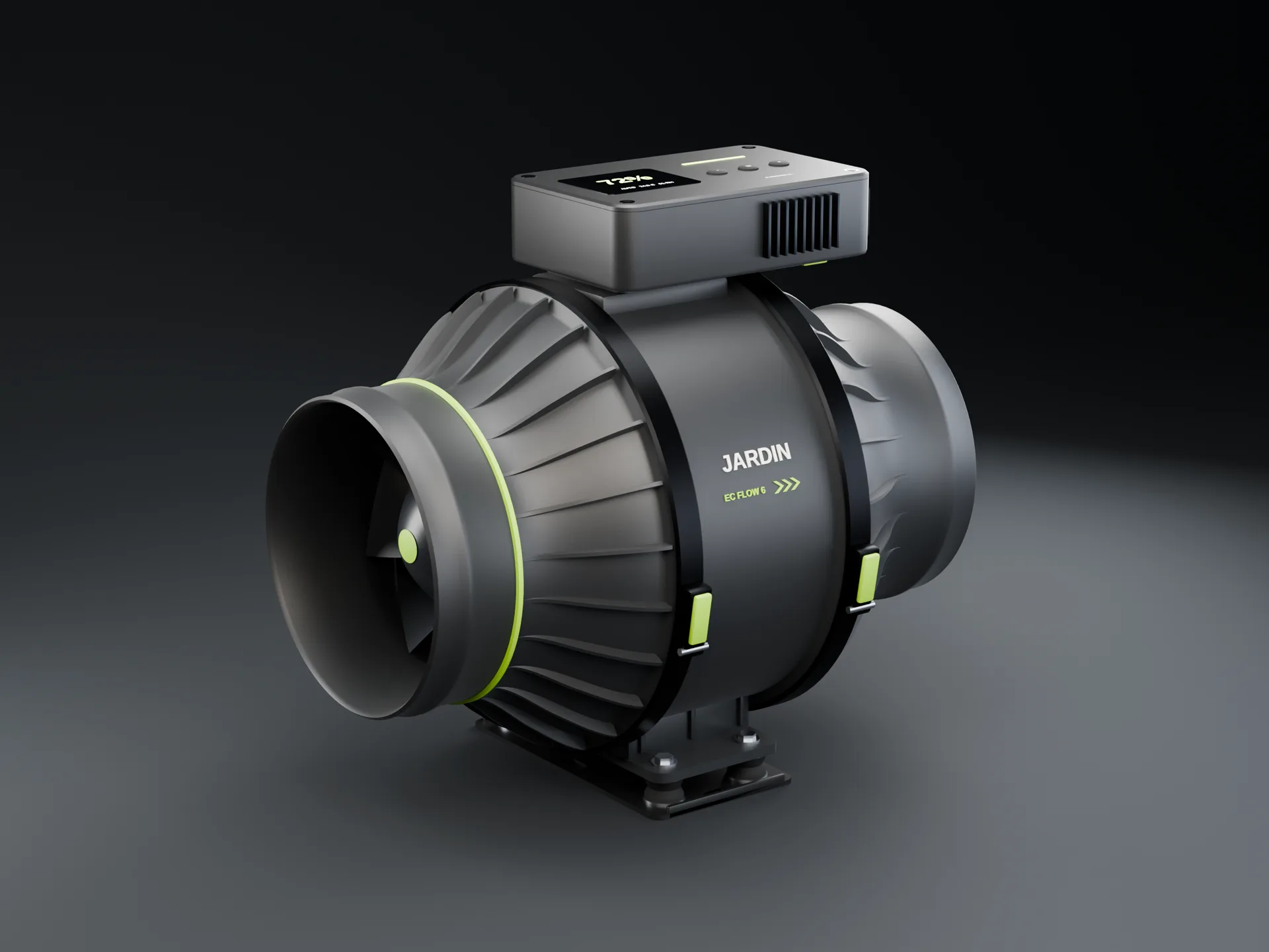 3D render
Front view · illustrative
- Model
- Free-air target
- At this speed
- Duct
- Impeller
- Controller
- L × W × H
- Made for
Side by side at true duct scale. "At this speed" is the middle of the free-air target range times the speed: a sketch, not a fan curve. Real curves come from a sample on a test rig.
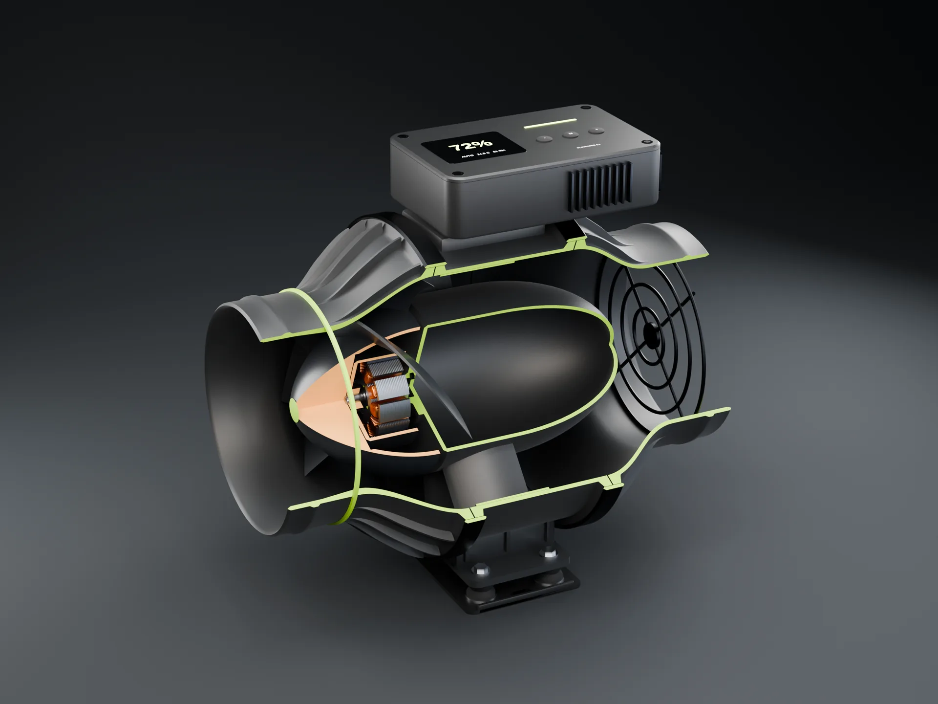
Cut it open · drag the green handle
Drag across the fan. Watch the air go through.
One camera, one fan, the impeller turning. Drag to cut away a quarter of the housing, the motor pod and the rotor bell. The blue path is the air, traced from the 3D model: in through the bellmouth, through the blades, round the motor pod, straightened by the vanes and out. The controller keys further down set how fast it turns.
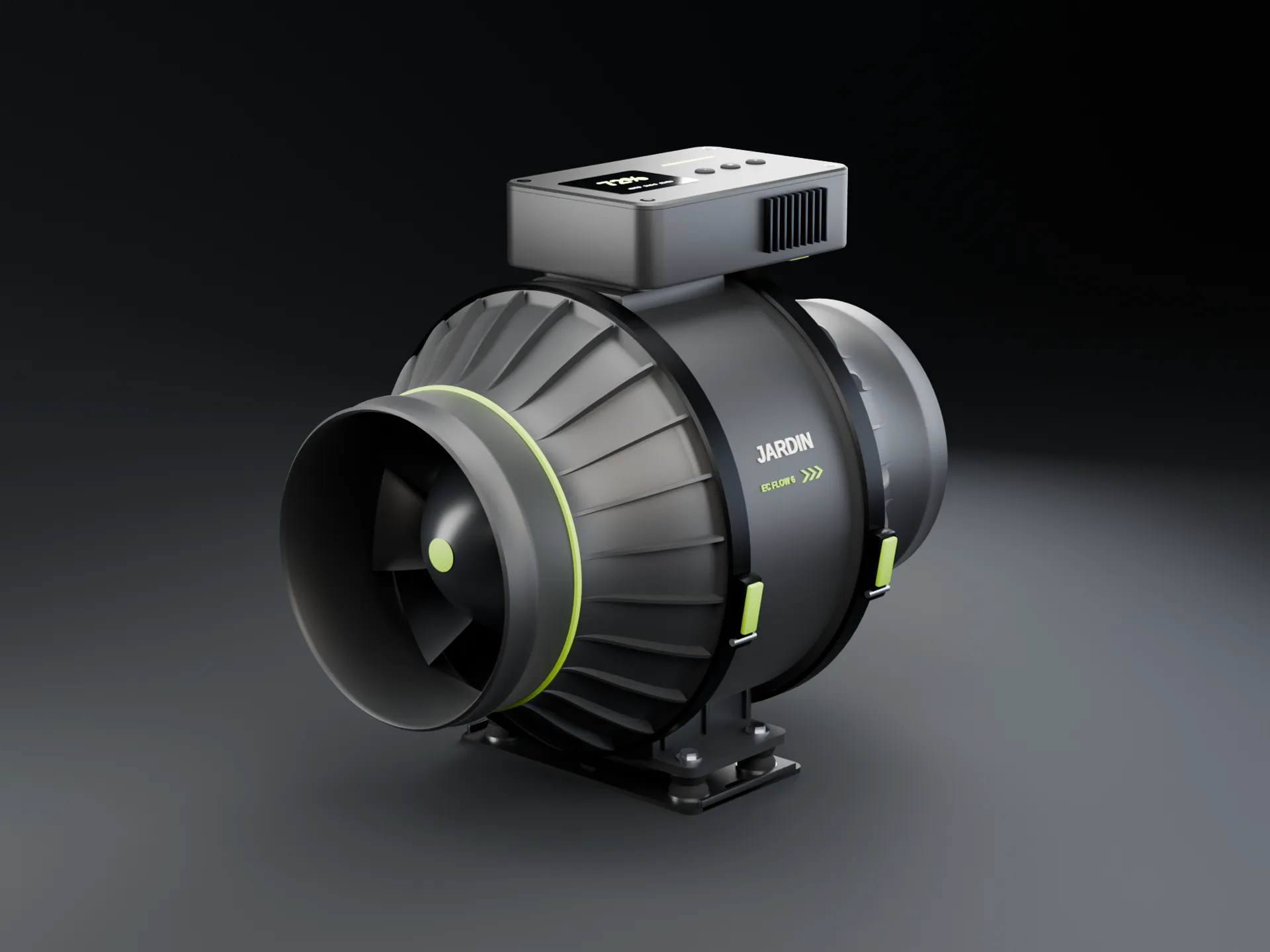
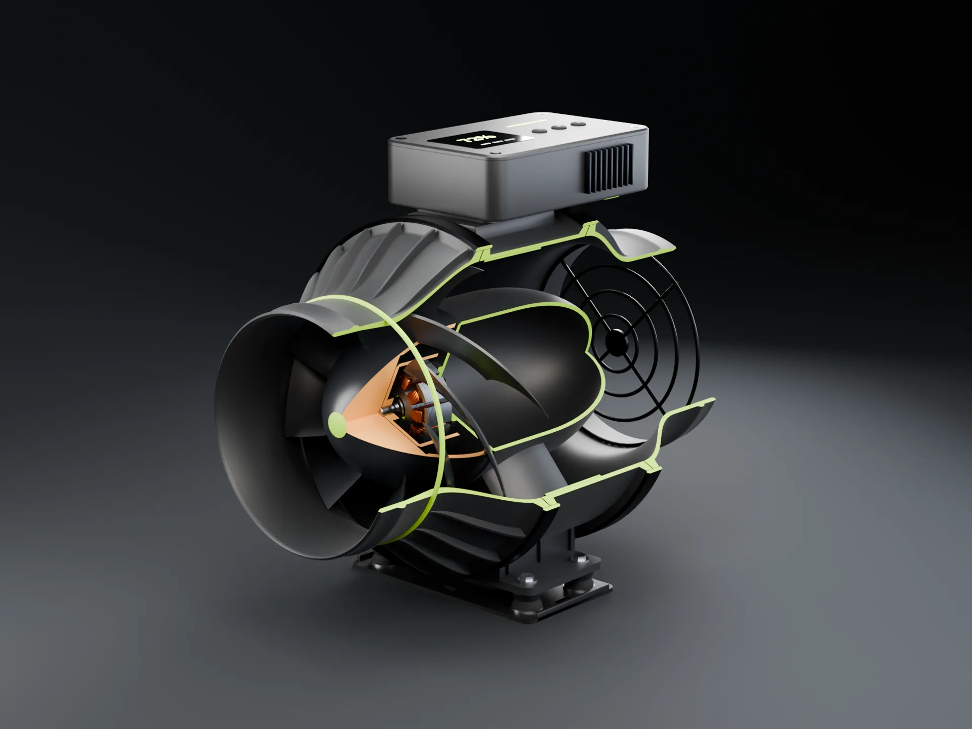
⇆
OutsideCut openEvery part, named · with its part number
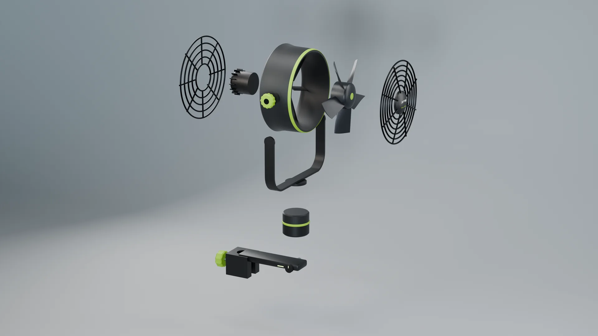
Taken apart. Every piece labelled.
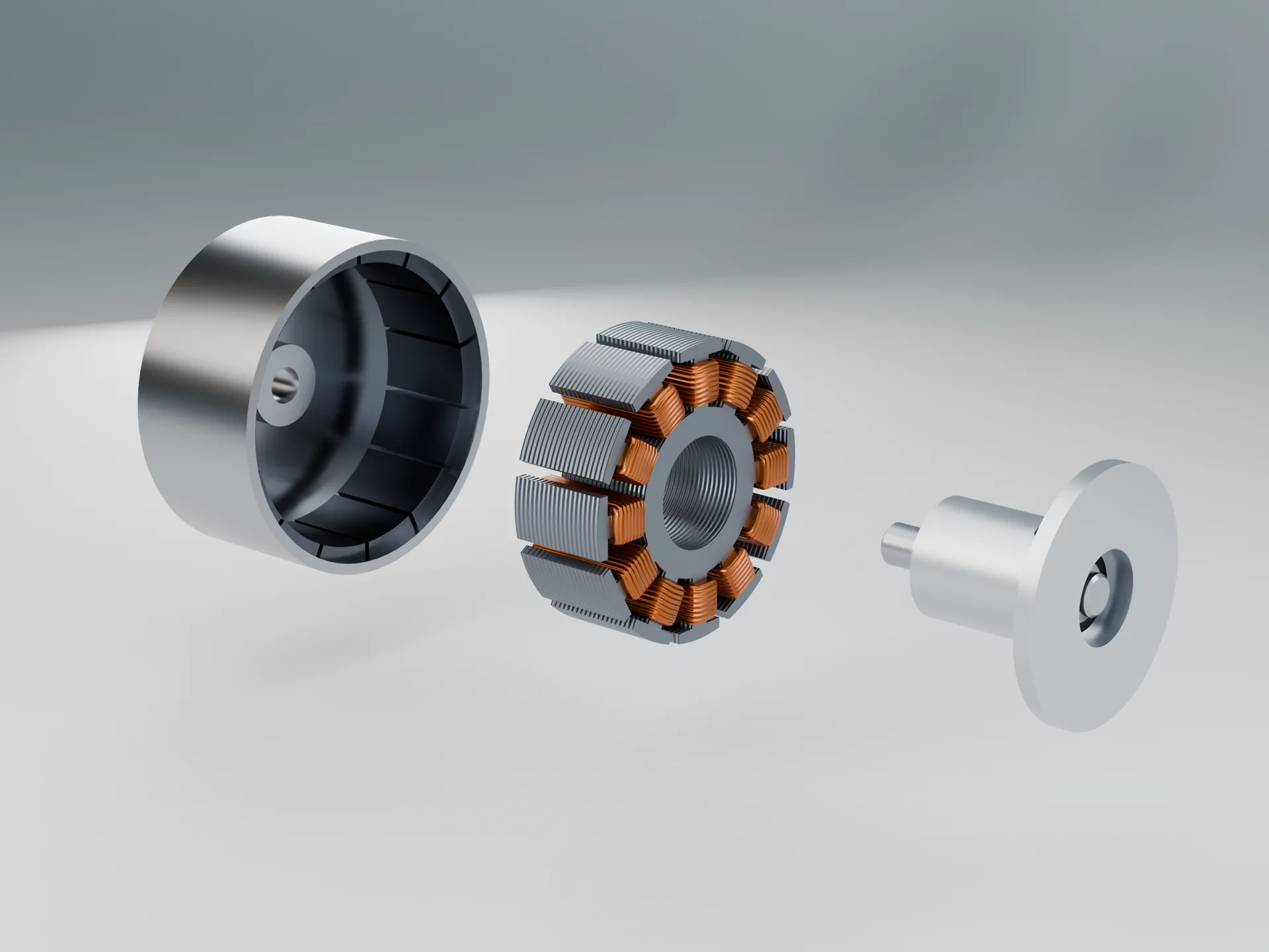
The labels come out of the 3D model itself: each one sits on its part and carries the part number the render was built from. Hover or tap a part, or take the tour and we'll zoom into each one.
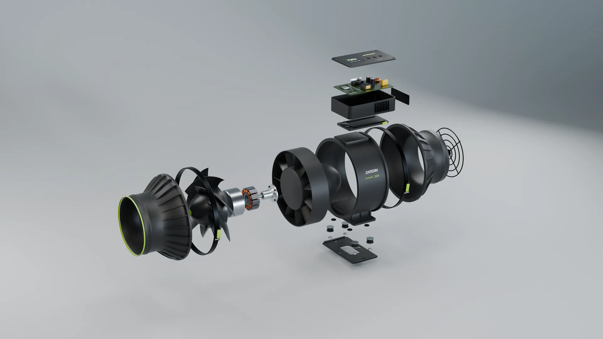
Tent builder · fit it out in 3D, watch the air Modelled
Put the fans where you would. See what the air does.
A J-series tent with its real ports: duct ports high and low on each side and in the roof, and the passive intake vents. Add as many exhaust fans, intake fans, EC Breezes and Flow Jets as you like. Switch any of them off, change sizes, turn them down, swing them or hold them still, and open or close every vent. The canopy colours show how hard the air moves across it: purple is still air, green is the gentle movement plants like, orange is too much.
Exhaust out
Fresh air in
Exhaust at night
Run-on after lights off
How many
Driver
still, under 0.1 m/slight
gentle, 0.3–1 m/sstrongtoo strongopen ventstreaks at half speed
Heat flowlight leaving the barslanding as heat: leaves, pot tops, floorwarm air rising off the fins, leaves and pots, carried to the exhausts
room air+4°F+8°F+13°F+20°F and up
0%of the canopy top in gentle air
0%of it in still air
0%in air that's too strong
0%under the canopy with air moving
–pressure
0CFM out the exhausts
0CFM pushed in by fans
0CFM the tent needs
0air changes a minute
–open vents and ports
Heat
0heat in the tent
–at the canopy top
–at the top of the tent
–leaving by the exhausts
–of the heat goes out the exhausts; the rest through the walls
–CFM out to hold the canopy
–where the exhausts draw from
–of light landing on the leaves
–warm air off the light's fins and driver
–of light getting past the leaves to the pots and floor
–on the pot tops
–in the root zone, about
–µmol/m²/s at the canopy, about
0exhaust air over room
–under the canopy, round the stems
Humidity and the night, from the simulation engine
–relative humidity in the canopy air, lights on
–leaf vapour pressure deficit (VPD), lights on
–dew point of the tent air
–tent air pressure against the room, in pascals
–water the plants transpire, litres per hour
–average light at the canopy top
–of the light's photons land on the leaves and buds
–peak relative humidity after lights off
–after lights off the peak comes
–lowest margin above the dew point, overnight
0 open vent area for the air the exhausts pull
Add to the tent
Start from
Let it work it out · same model, many tries
In the tent · tap a part for its settings
Vents and ports · tap to open or close
Modelled: a coarse 3D sketch of the air, not a CFD simulation. The tent's inside is cut into cells of about 4 to 10 cm and the air and its heat are worked out together, step by step: each Breeze, Flow Jet or intake fan pushes the air at its outlet the way it points (and swings, if you set it to), the leaves slow the air in the top 35 cm of the canopy and the stems below it, warm air rises, and the air is kept from piling up or crossing the tent's walls. Each exhaust draws the air in over its whole carbon filter; open vents and spare ports share, by area, whatever the exhausts pull beyond the intake fans. Ports and vents are where the J-series tent model puts them. The read-outs, the maps and the best set-up come from a run of the same model settled over one full swing of the fans, so the same set-up always reads the same. Fan air, the temperatures, the humidity and the night read-outs come from the Jardin simulation engine: the tent as two stacked bodies of air with its fans, filters, vents, light and plants, all on estimated inputs (no Jardin hardware has been measured yet). The 3D picture of where the heat sits is scaled to its canopy-air and top-of-tent temperatures. "CFM the tent needs" is the exhaust flow that holds the canopy at the temperature you set (never under one air change a minute), from the same engine; our ventilation guide has the rules of thumb behind it. All fan figures are design targets. Lumen figures are the kits' first-pass calculations; the HPS and CMH lines are typical figures for comparison.
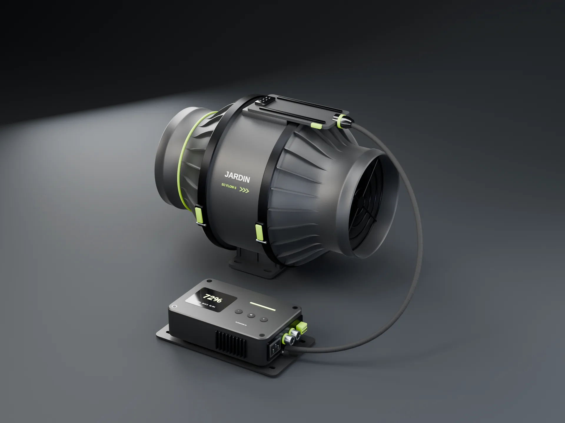
FlowCore controller · slides off the fan
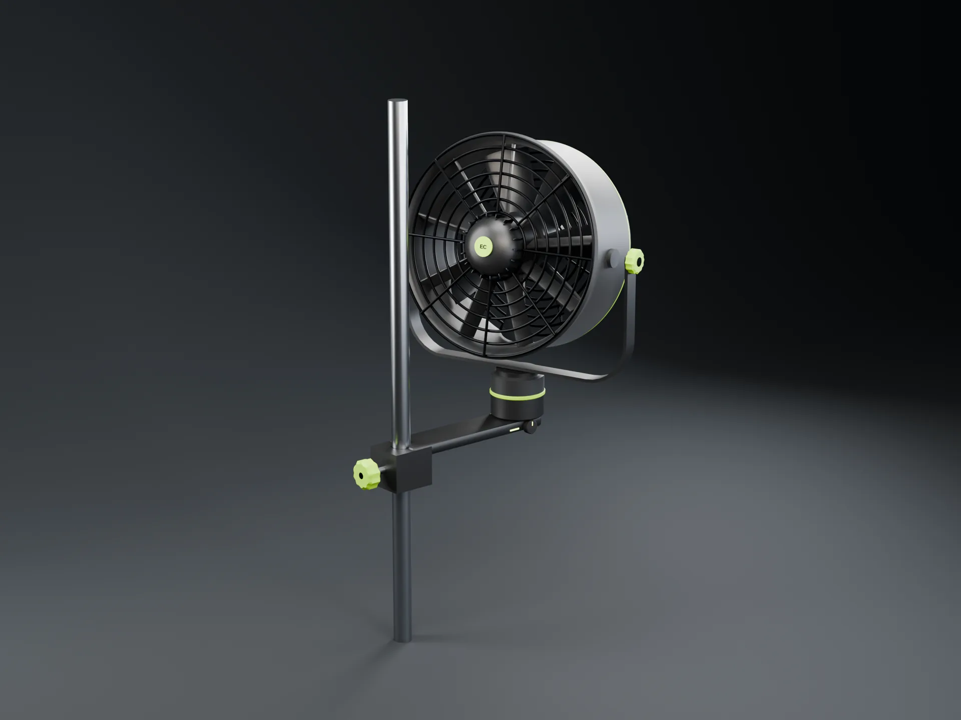
Fan in the roof. Controls on the wall.
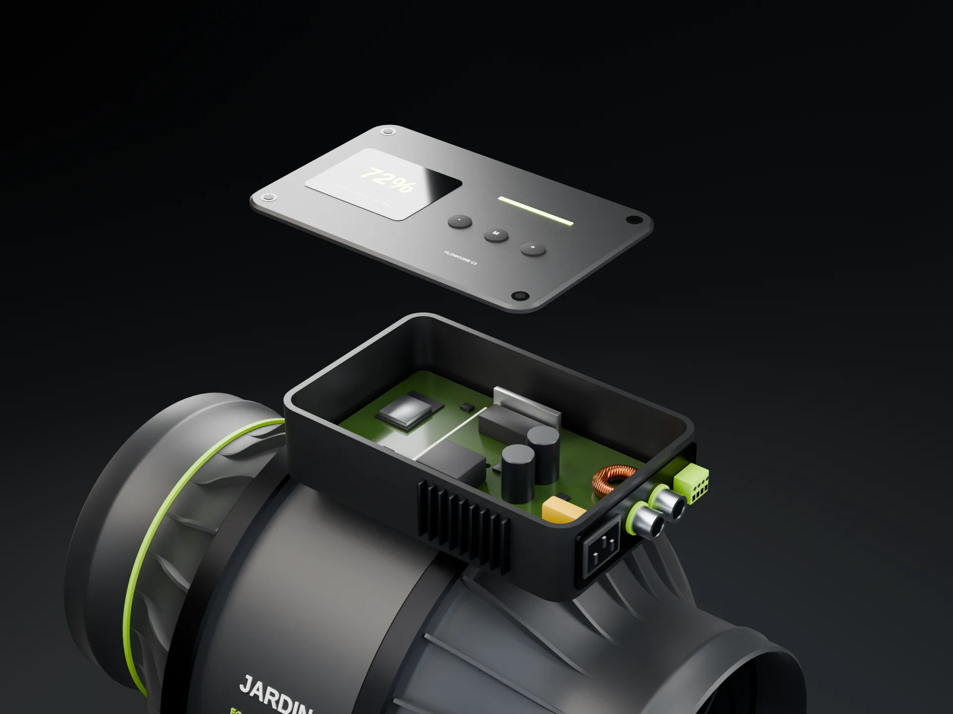
The controller sits on a dock on the fan: two slide rails, a green release latch and a blind-mate connector. Slide it off and it clips onto a wall plate with the same dock, joined by a cable, so the display and keys live outside the tent.
3D renderMANUAL
70%
One connector panel: mains in, two Jardin Core bus ports (or RS-485 / Modbus RTU) and a terminal block for 0–10 V, PWM, tach and fault. It runs from the Jardin app or from the controller you already own. These keys also drive every fan speed on this page.
A demo, not firmware. The wall plate and cable are accessories; the cable length is not decided yet.
The range · one collar per duct size
Fans, filters, circulation, and the parts between.
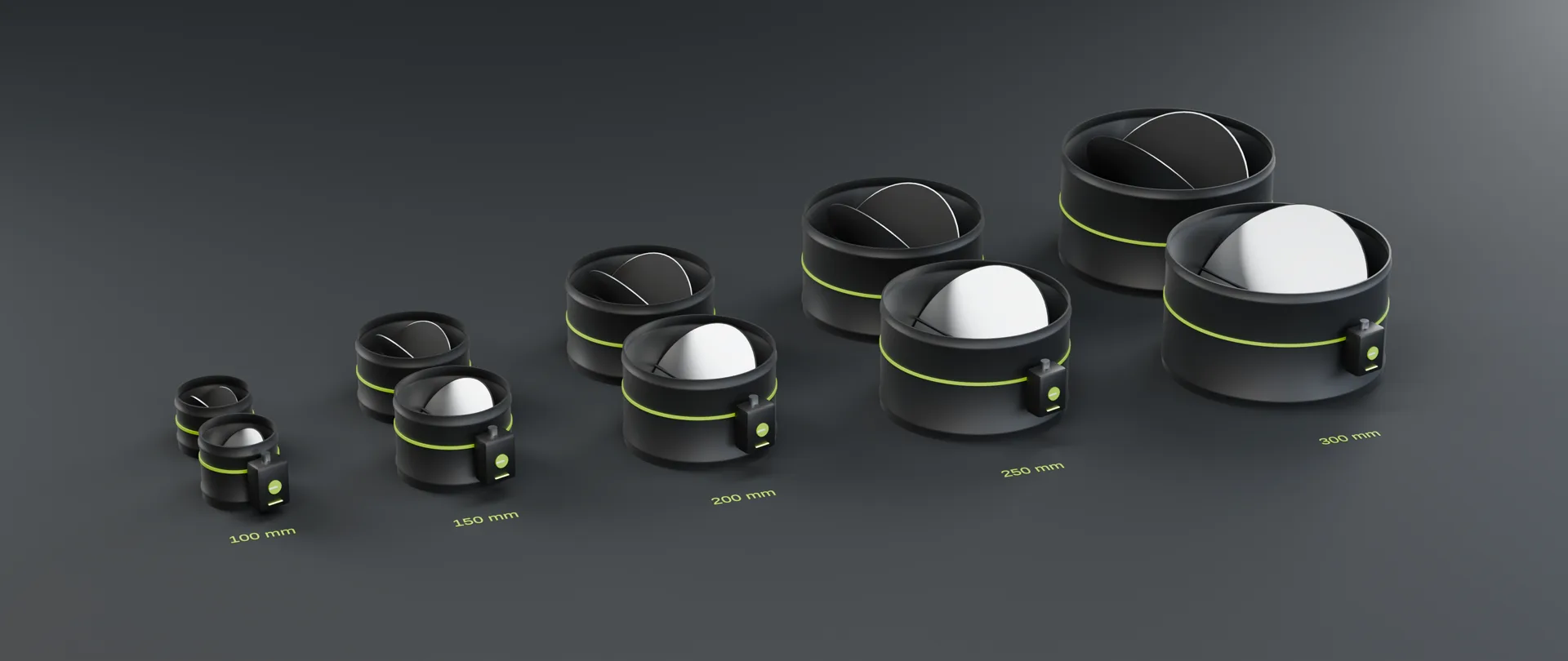
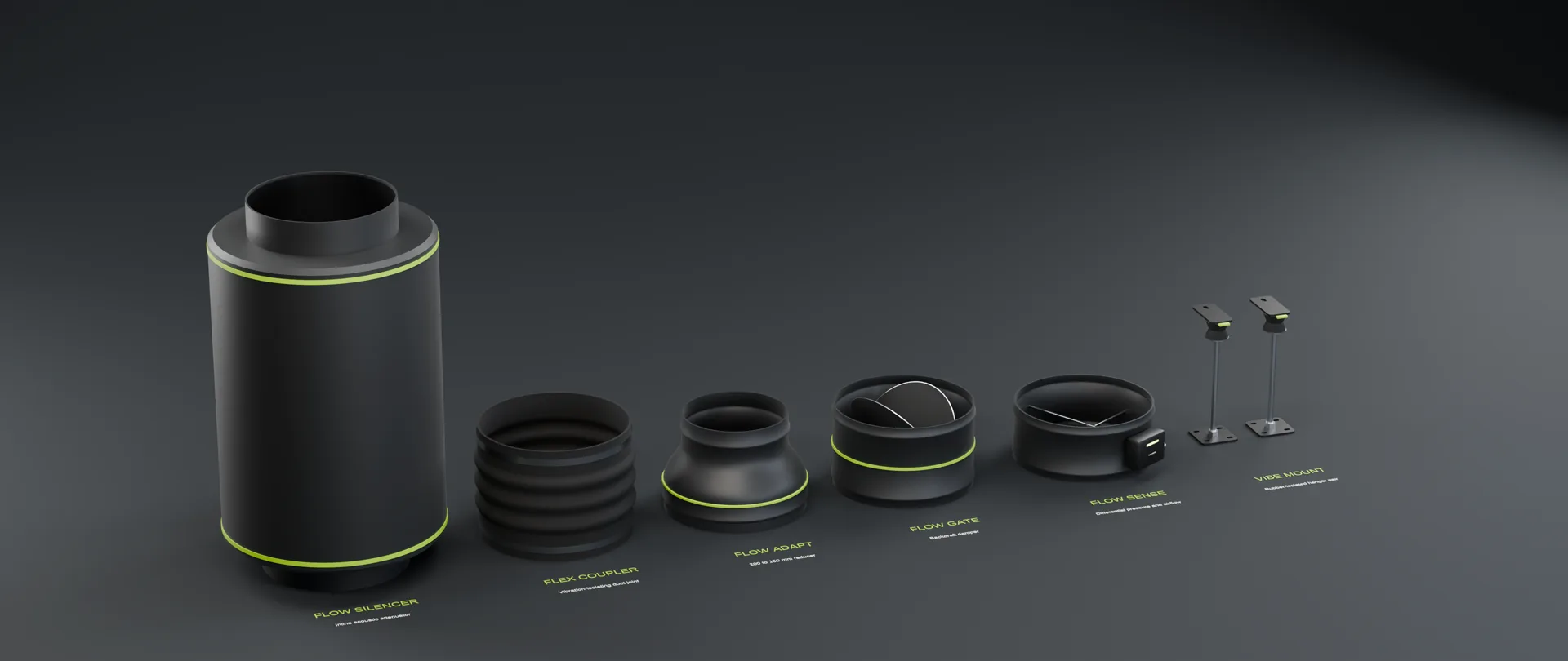
Every fan, filter and flow part ends in the same beaded collar for its duct size, so one duct and one coupler fit all of them.
3D render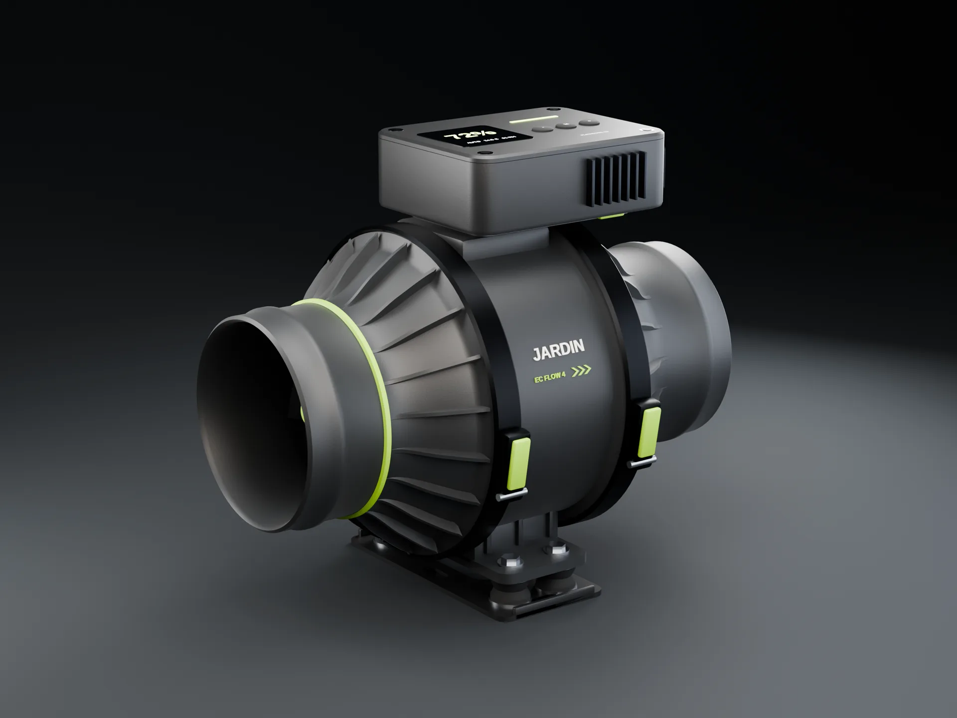
EC Flow 4
150–220CFM target
Small tents, propagation, cabinets
- Duct
- 100 mm
- Length
- 244 mm
- Controller
- FlowCore C0
- Blades / vanes
- 7 / 11
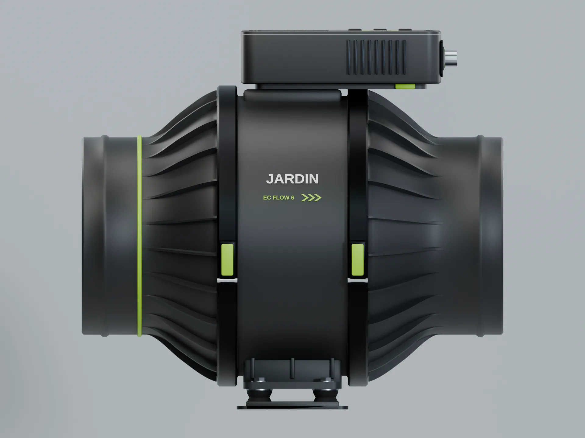
EC Flow 6
350–500CFM target
Compact efficiency
- Duct
- 150 mm
- Length
- 316 mm
- Controller
- FlowCore C1
- Blades / vanes
- 7 / 11
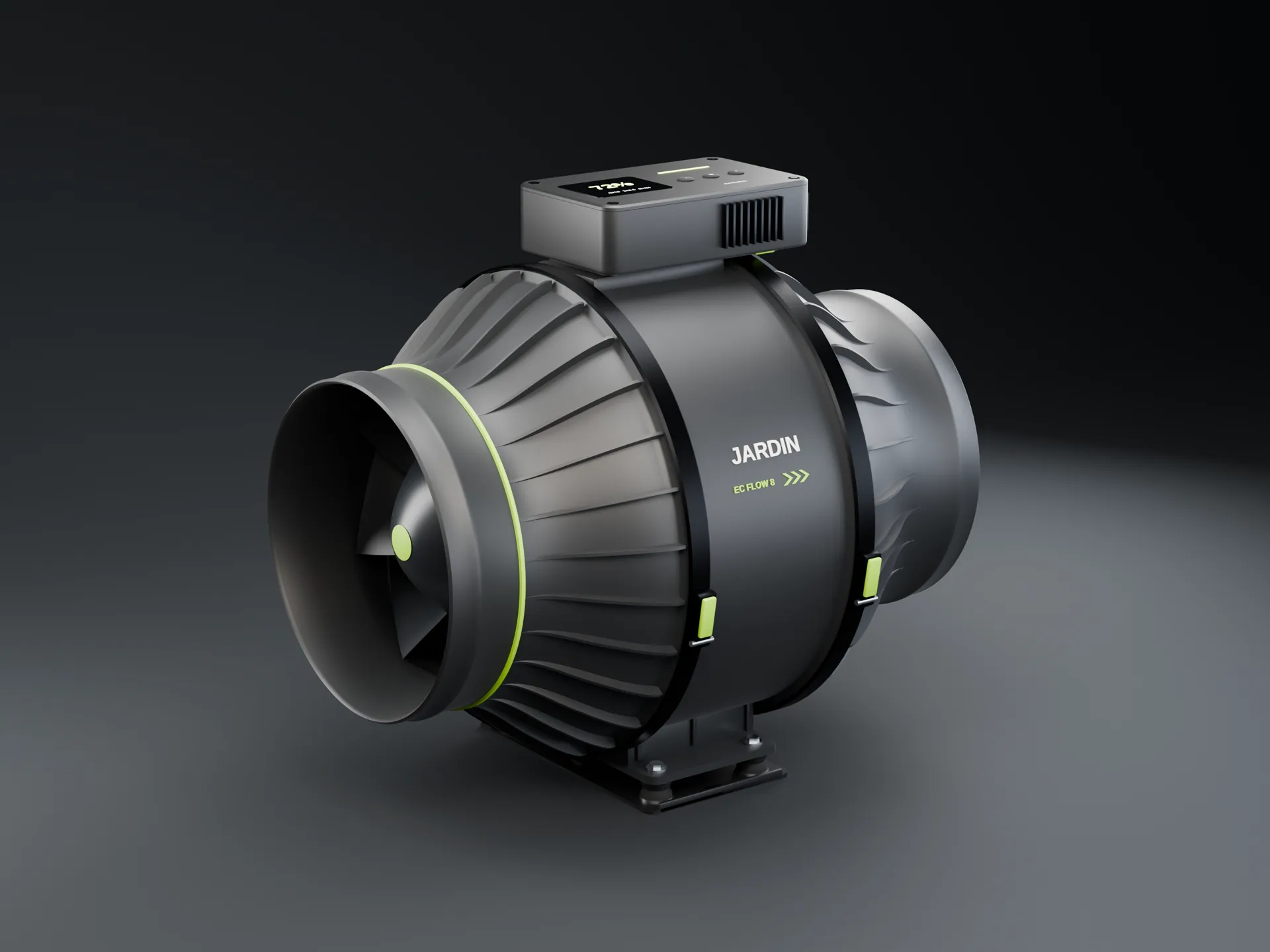
EC Flow 8
600–850CFM target
General purpose
- Duct
- 200 mm
- Length
- 387 mm
- Controller
- FlowCore C1
- Blades / vanes
- 7 / 11
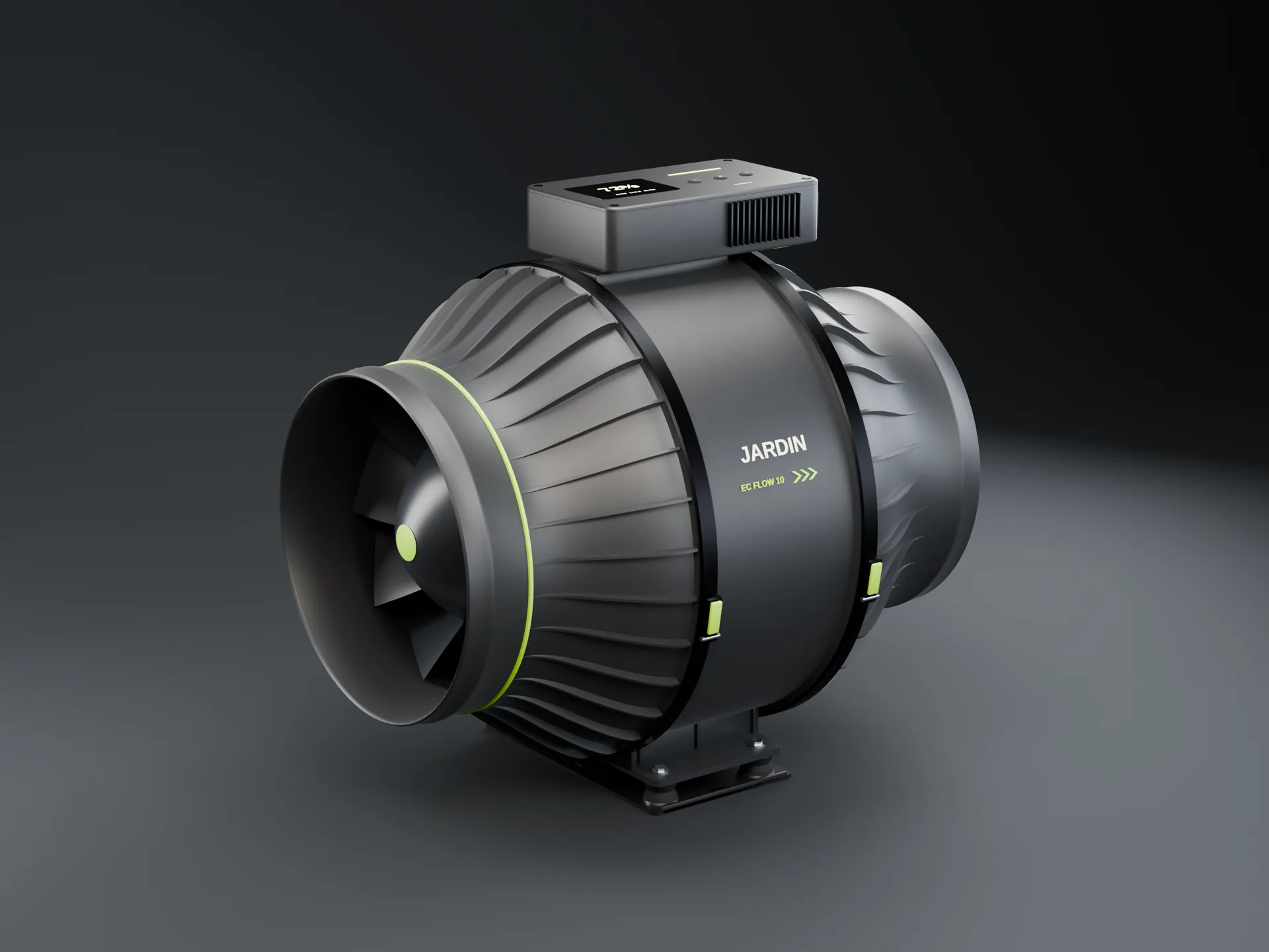
EC Flow 10
900–1,250CFM target
Higher volume
- Duct
- 250 mm
- Length
- 458 mm
- Controller
- FlowCore C2
- Blades / vanes
- 9 / 13
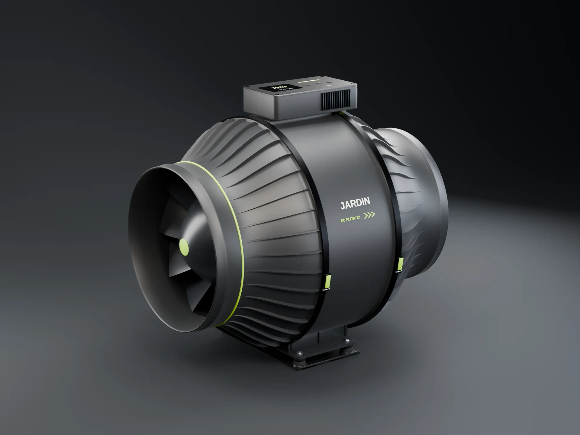
EC Flow 12
1,300–1,800CFM target
Large installations
- Duct
- 300 mm
- Length
- 529 mm
- Controller
- FlowCore C2
- Blades / vanes
- 9 / 13
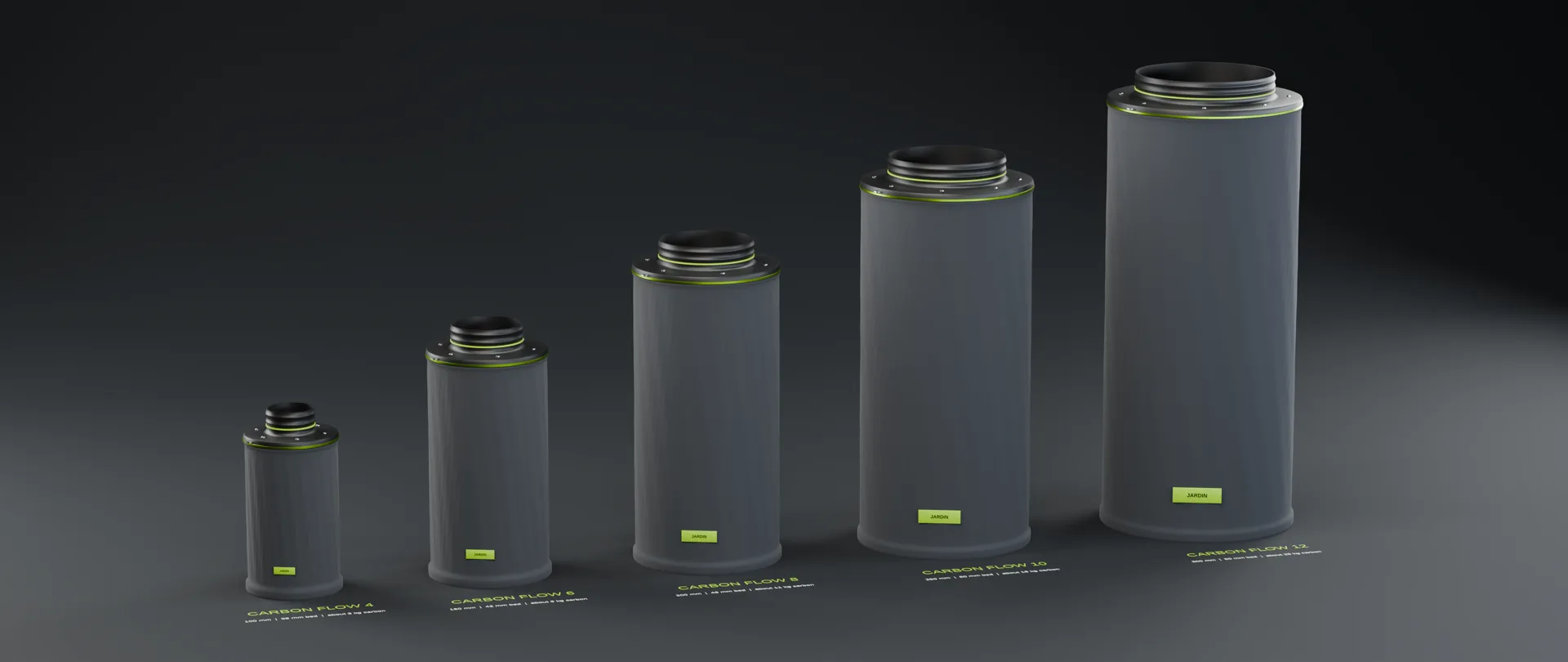 3D render
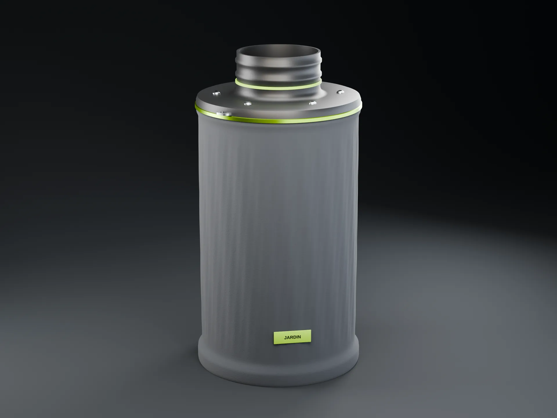
Carbon Flow 4
5.2L of carbon
Paired with the EC Flow 4
- Duct
- 100 mm
- Size
- 194 × 381 mm
- Bed depth
- 38 mm
- Carbon
- about 2.6 kg
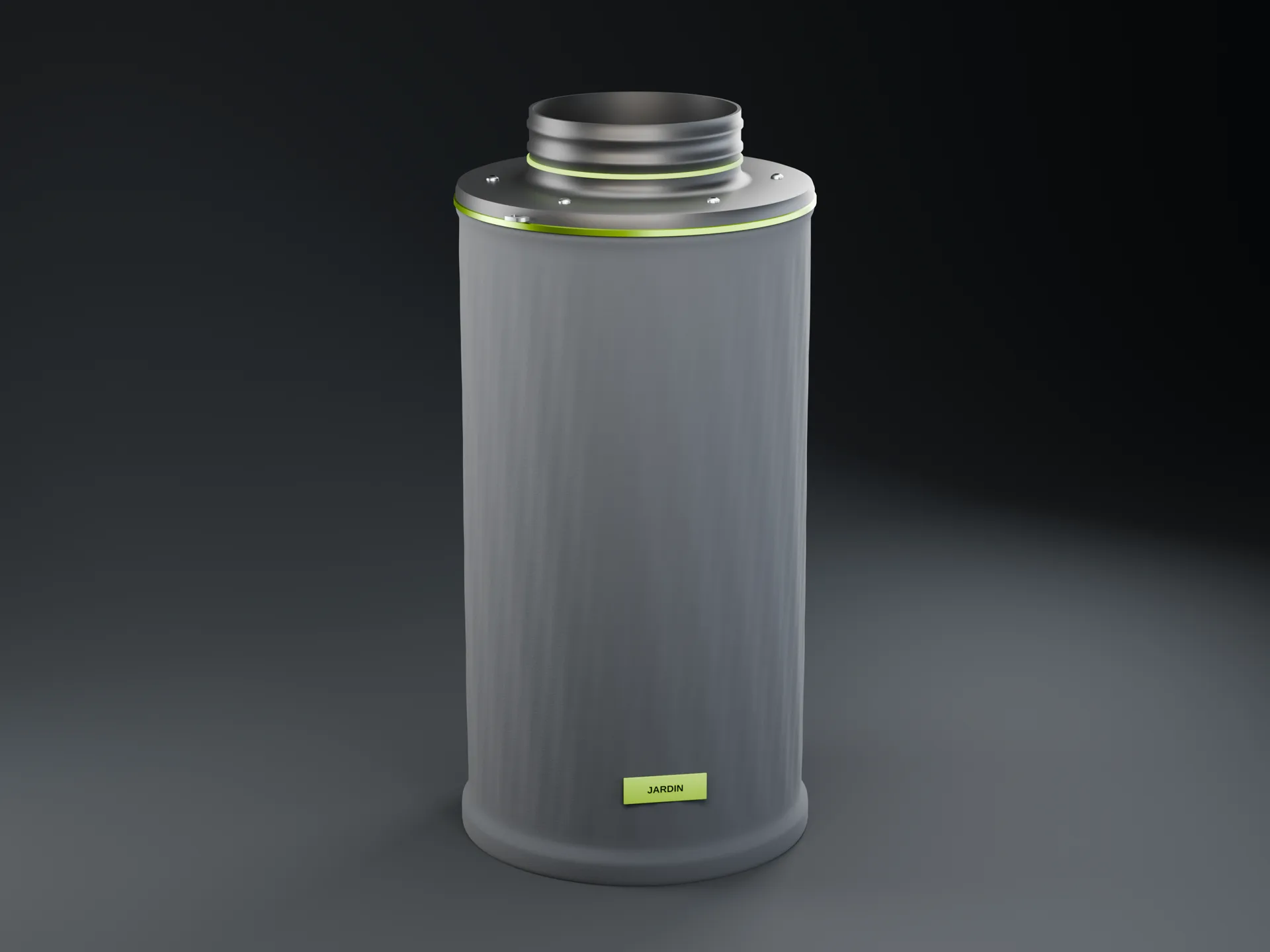
Carbon Flow 6
11.9L of carbon
Paired with the EC Flow 6
- Duct
- 150 mm
- Size
- 252 × 532 mm
- Bed depth
- 42 mm
- Carbon
- about 5.9 kg
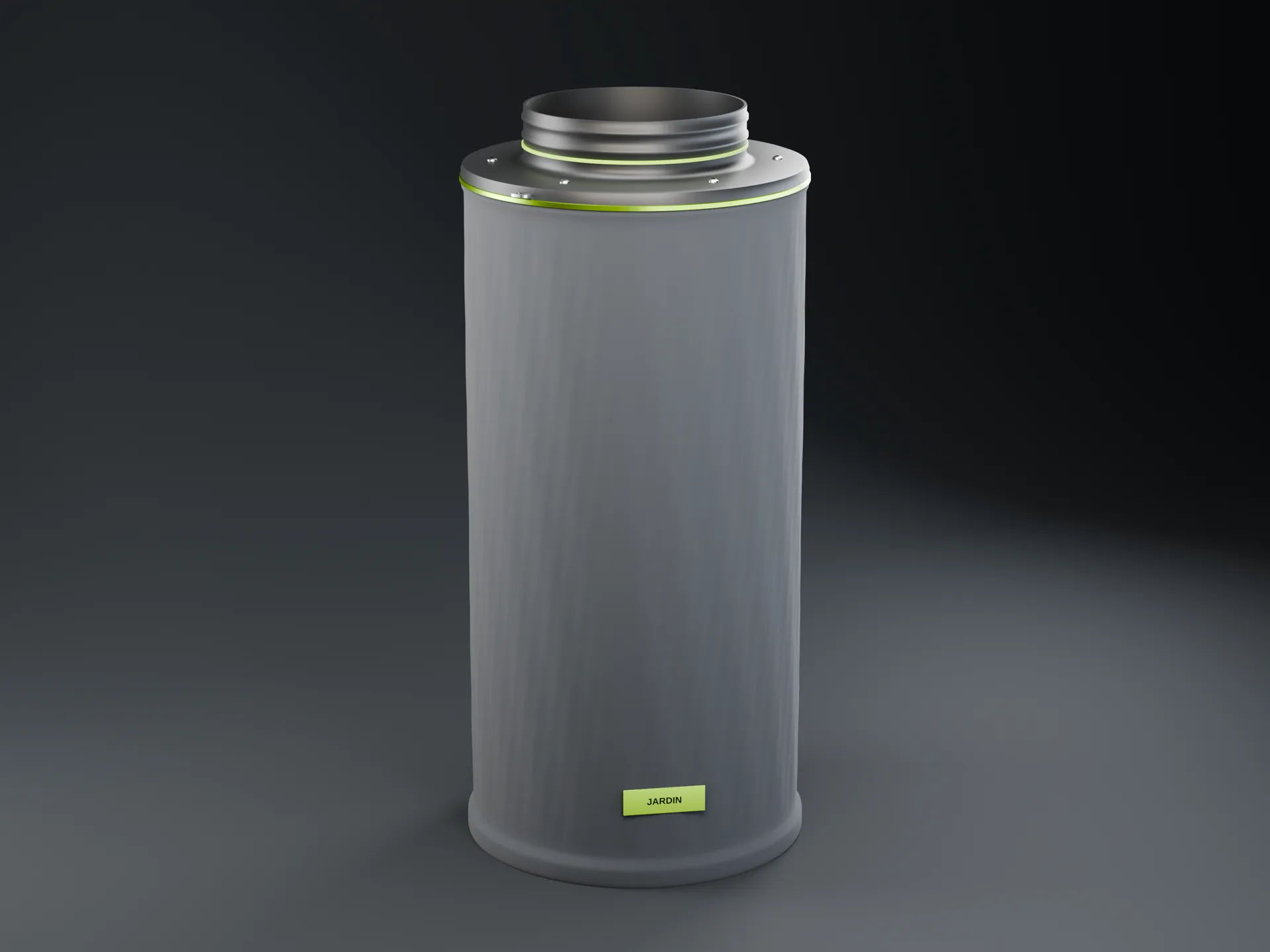
Carbon Flow 8
22.0L of carbon
Paired with the EC Flow 8
- Duct
- 200 mm
- Size
- 310 × 683 mm
- Bed depth
- 46 mm
- Carbon
- about 11.0 kg
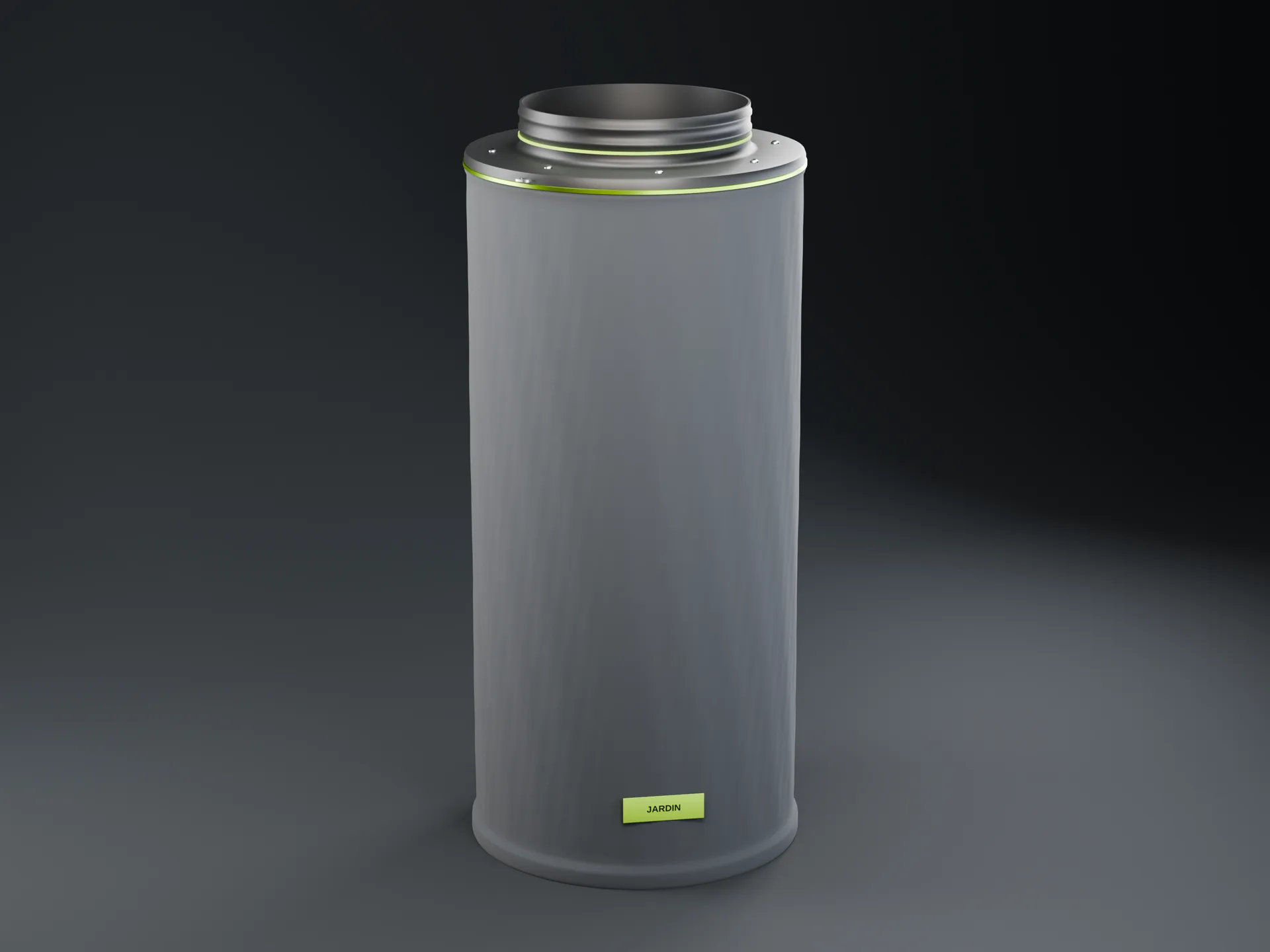
Carbon Flow 10
36.3L of carbon
Paired with the EC Flow 10
- Duct
- 250 mm
- Size
- 368 × 835 mm
- Bed depth
- 50 mm
- Carbon
- about 18.1 kg
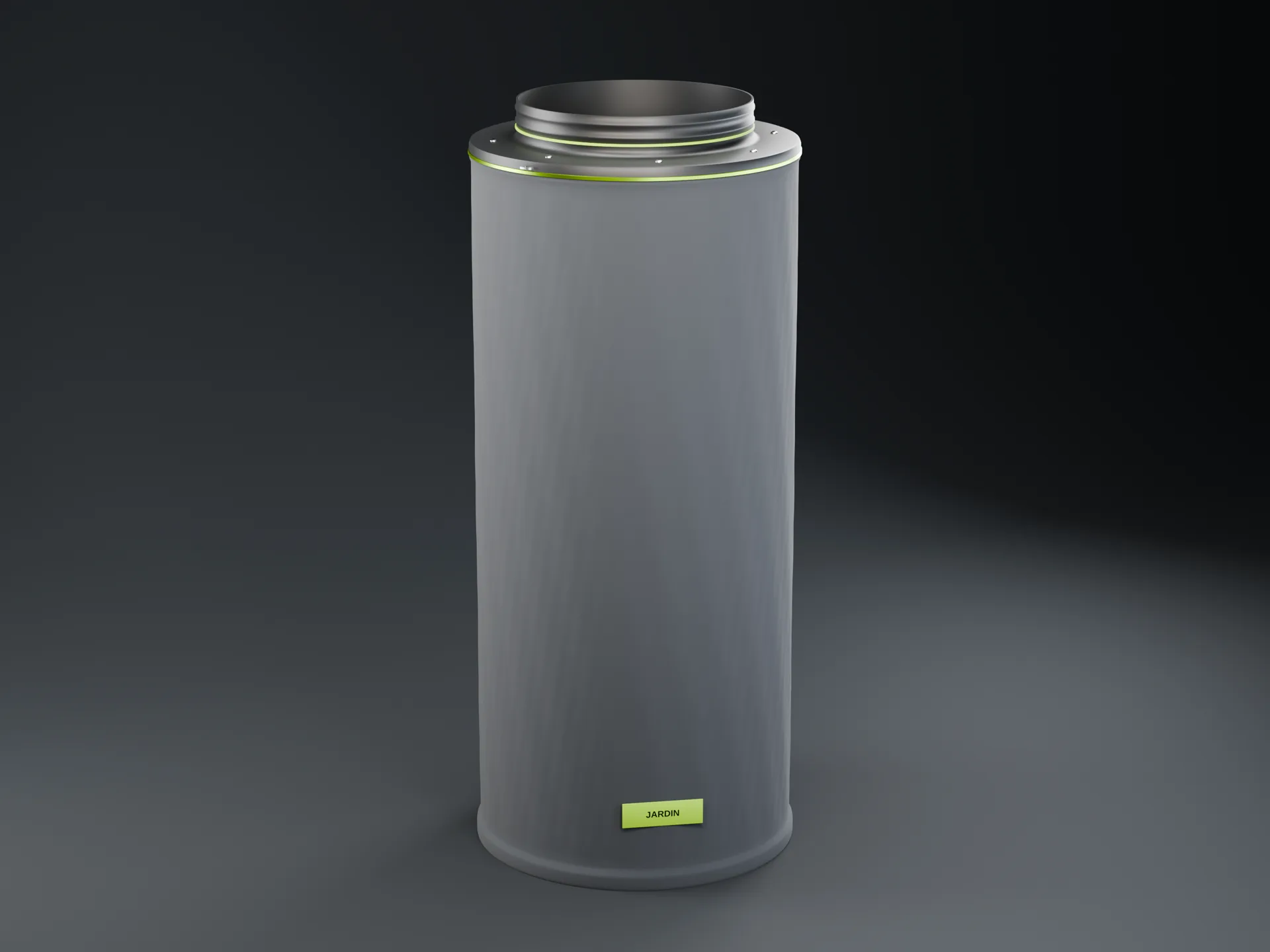
Carbon Flow 12
50.6L of carbon
Paired with the EC Flow 12
- Duct
- 300 mm
- Size
- 418 × 986 mm
- Bed depth
- 50 mm
- Carbon
- about 25.3 kg
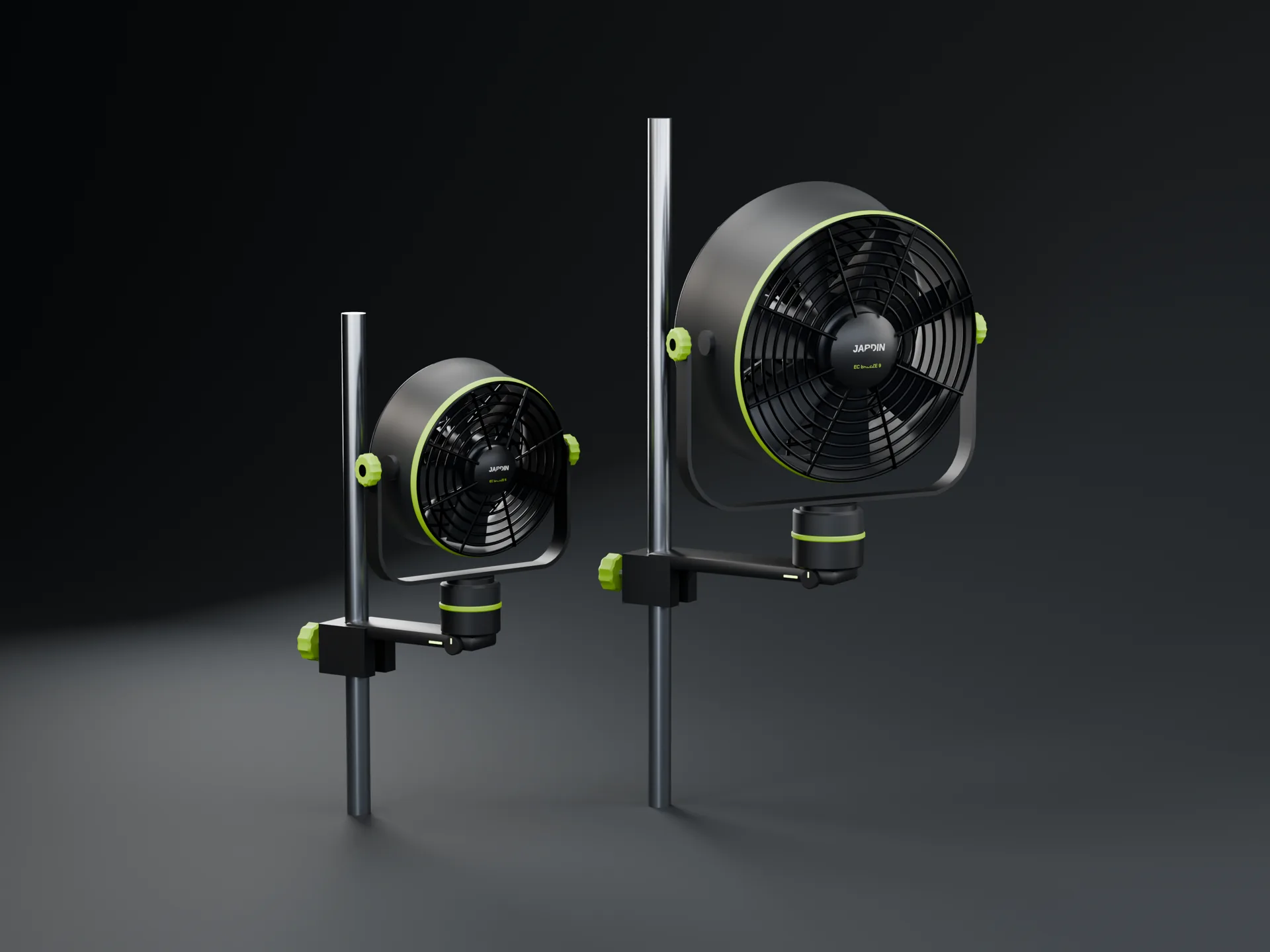 3D render
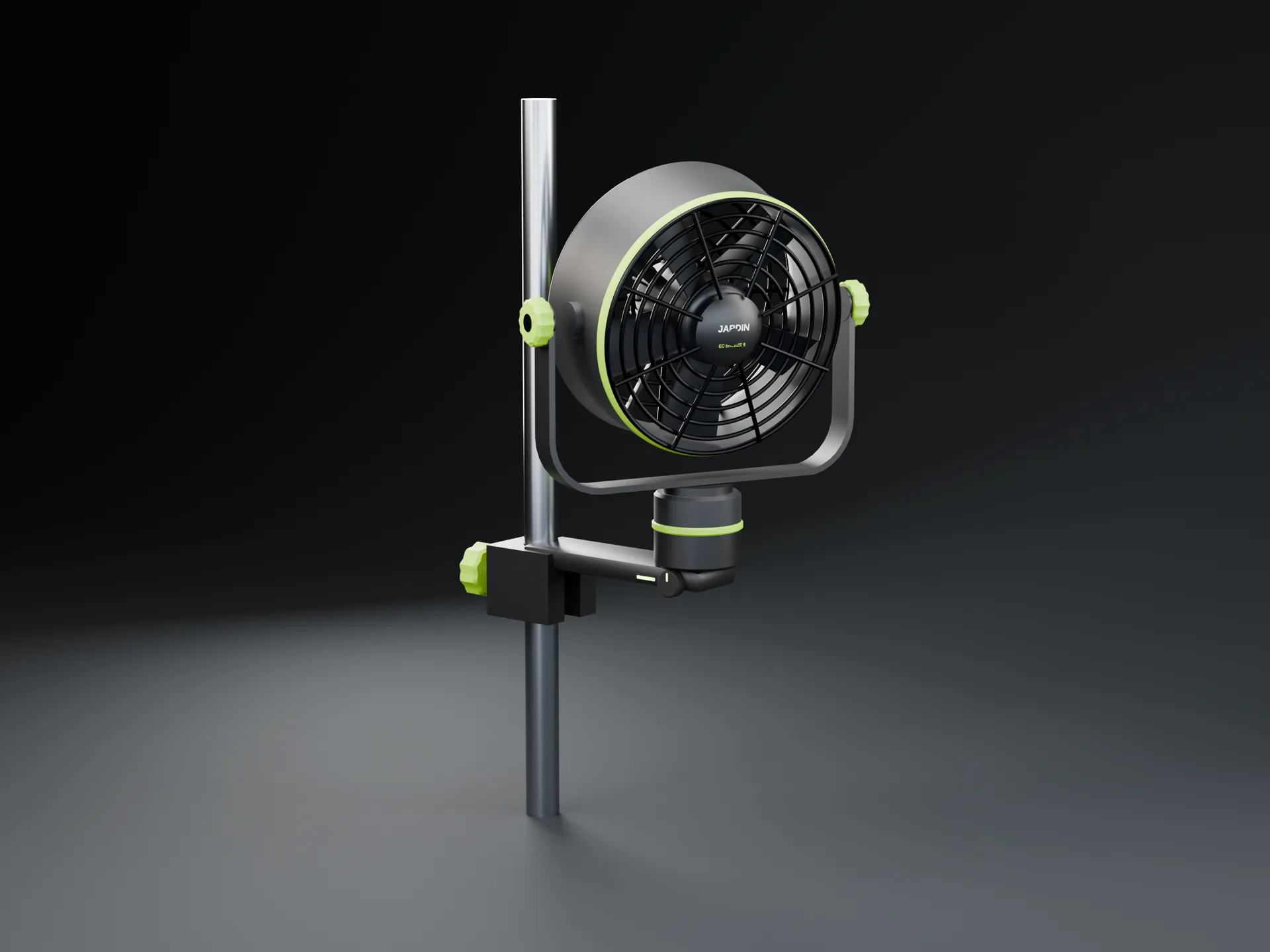
EC Breeze 6
200–300CFM target
2x2 to 4x4 tents
- Rotor
- 150 mm
- Blades
- 5
- Swing
- 0 / 45 / 90 / 120°
- Mount
- 22 mm pole clamp
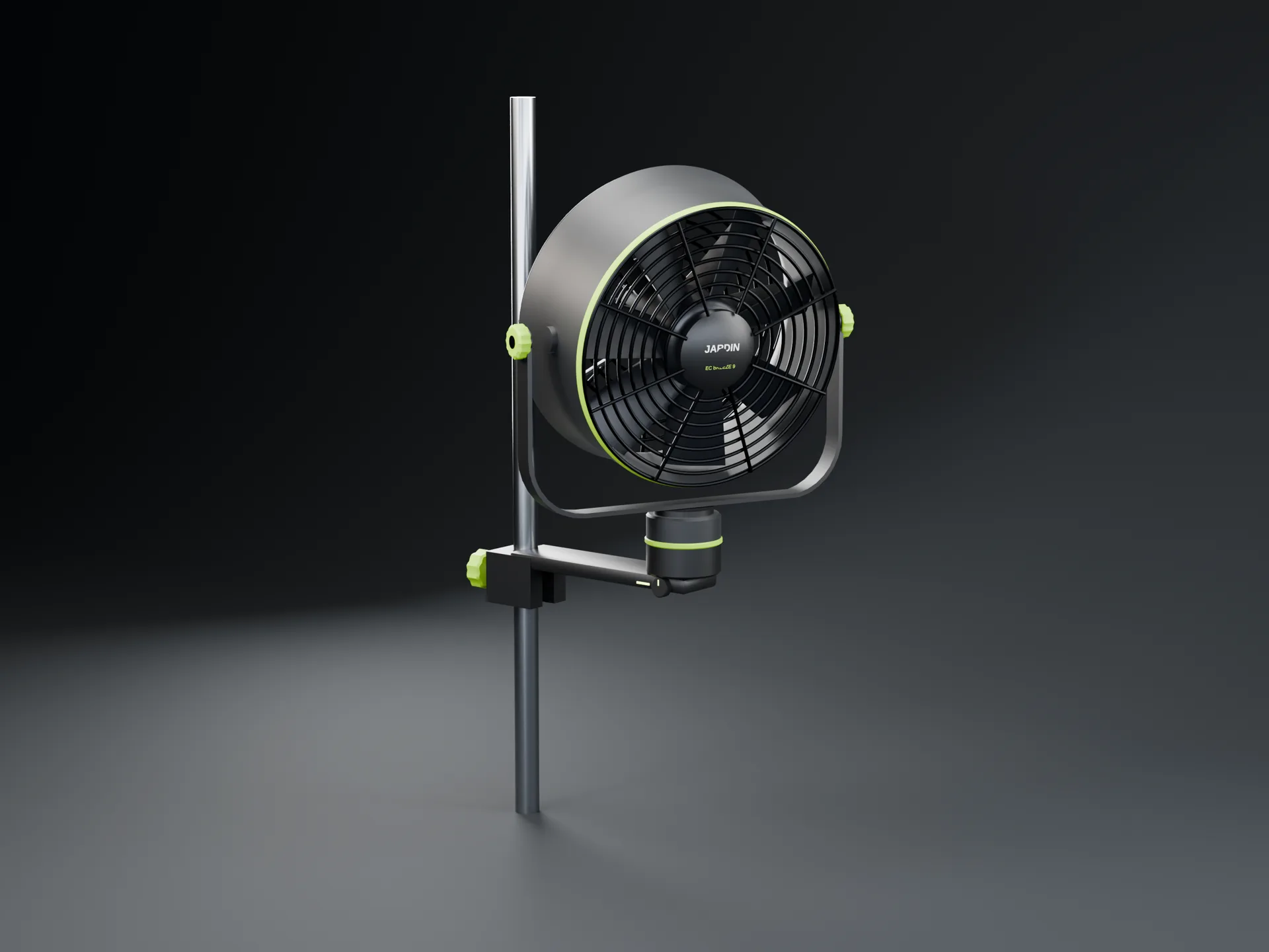
EC Breeze 9
500–700CFM target
4x4 and larger
- Rotor
- 230 mm
- Blades
- 7
- Swing
- 0 / 45 / 90 / 120°
- Mount
- 22 mm pole clamp
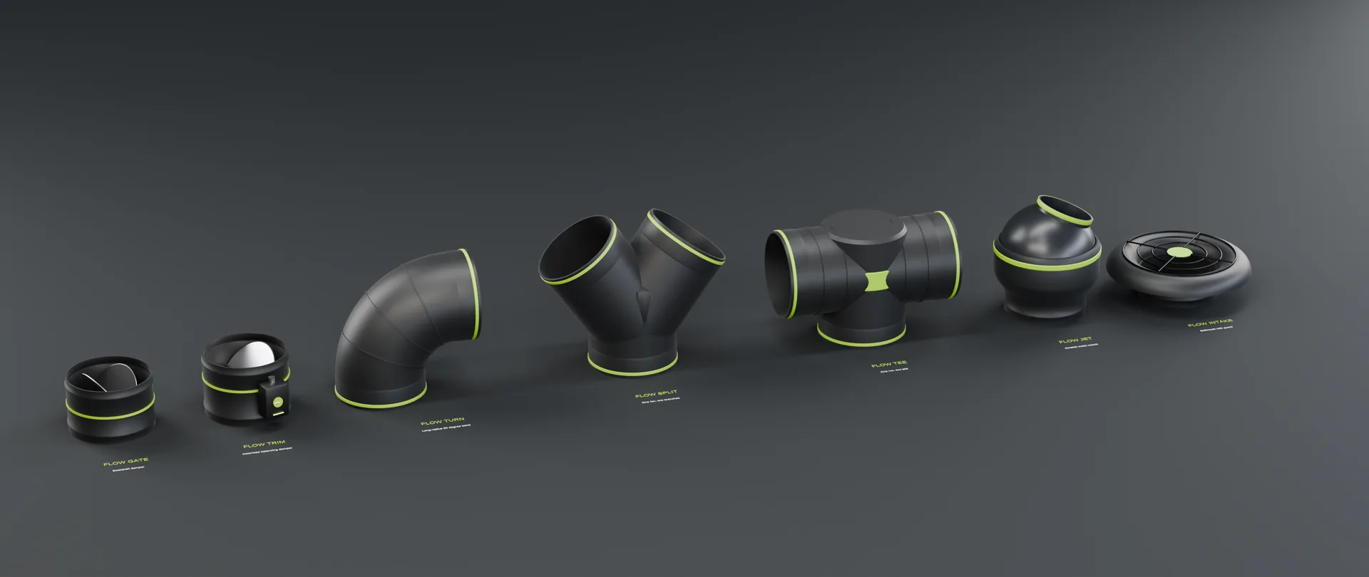 3D render
Flow Gate
Spring-return backdraft damper
JF-ACC-BDD-<duct>
100, 150, 200, 250 and 300 mm
Flow Trim
Motorised butterfly damper to balance a branch
JF-ACC-TRM-<duct>
100, 150, 200, 250 and 300 mm
Flow Turn
Long-radius 90° bend, socket each end
JF-ACC-TRN-<duct>
100, 150, 200, 250 and 300 mm
Flow Split
One in, two out, to feed two corners from one fan
JF-ACC-SPL-<duct>
100, 150, 200, 250 and 300 mm
Flow Tee
One in, two out at right angles: two Flow Jets on one run
JF-ACC-TEE-<duct>
100, 150, 200, 250 and 300 mm
Flow Jet
Ball nozzle in a socket ring, aimed by hand
JF-ACC-JET-<duct>
100, 150, 200, 250 and 300 mm
Flow Intake
Bellmouth with a guard for an open duct end
JF-ACC-INT-<duct>
100, 150, 200, 250 and 300 mm
Filter bed volume and carbon mass are arithmetic from the drawn geometry at an assumed 0.5 kg/L. They are not odour, pressure-drop or service-life figures; those come when a filter is built and tested with a chosen carbon grade.
Why it's built this way
Decisions you can see.
Six choices in the drawings, and the reason for each.
01
Tool-free service
Two over-centre clamp bands hold the three housing sections. Open the front band and the inlet, impeller, rotor and stator come out the front. The controller has its own four-screw cover, so a failed controller is a controller swap.
02
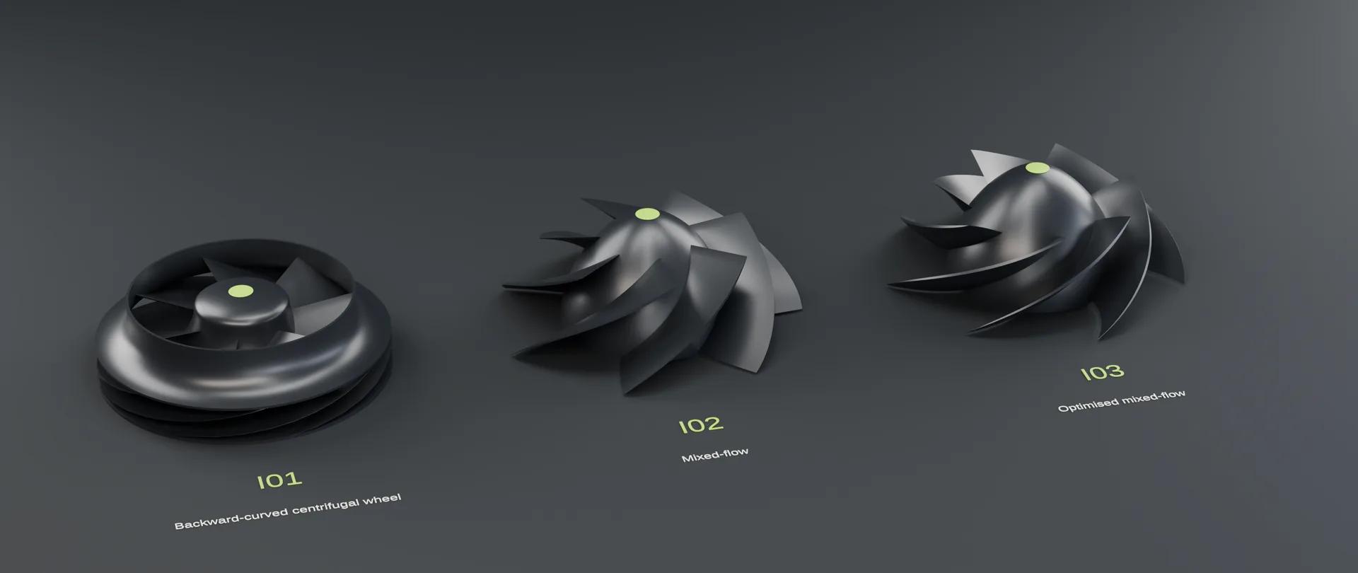
Three impellers drawn, one chosen
A backward-curved centrifugal wheel, an even-pitch mixed-flow wheel and the forward-swept, uneven-pitch I03. All five fans use I03, so its tone spreads instead of whining.
03
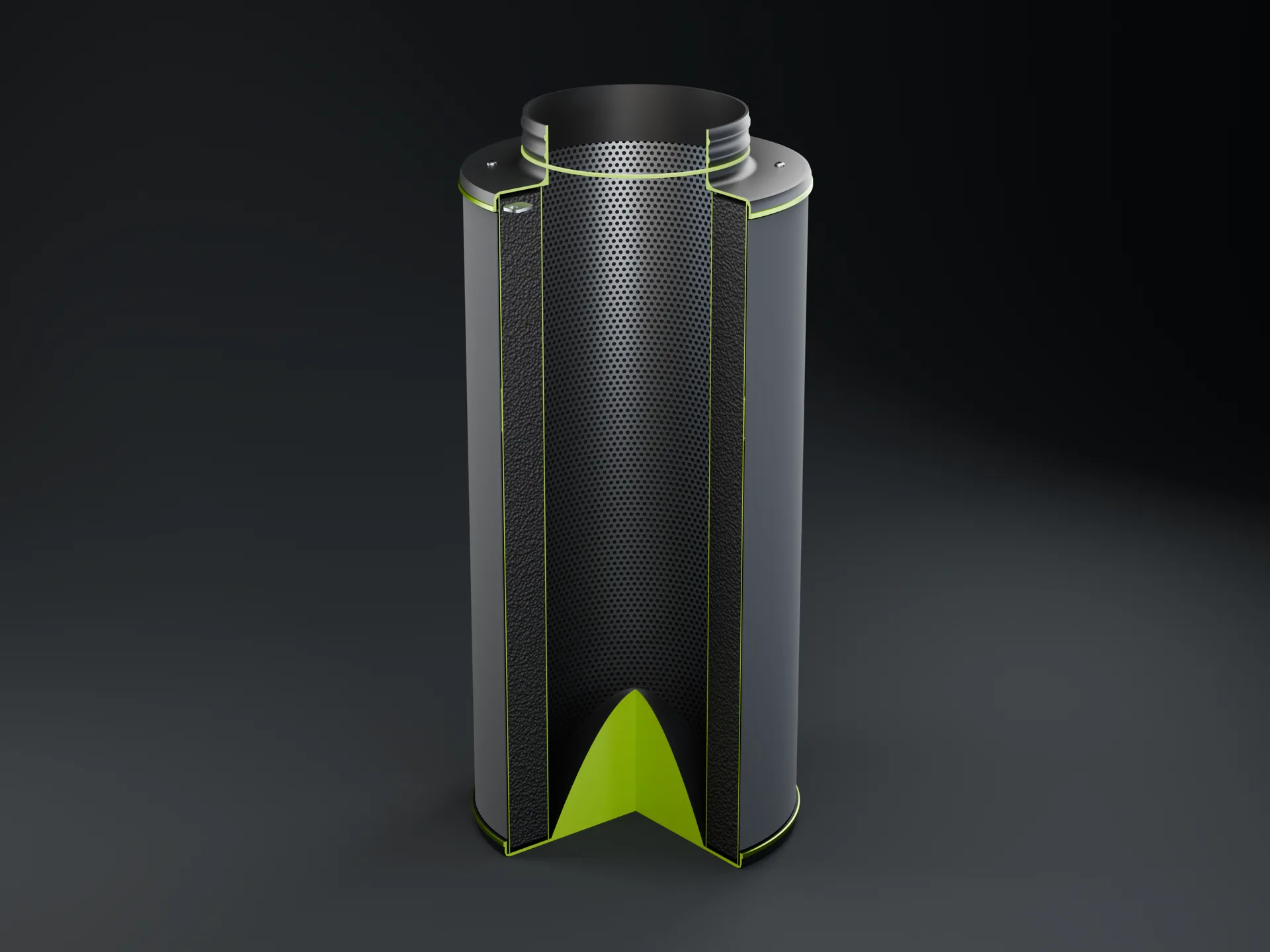
A filter on the same collar
Air crosses the sleeve, the perforated shell and the carbon bed, turns up the core past a flow cone and leaves through the same beaded collar as the fan.
04
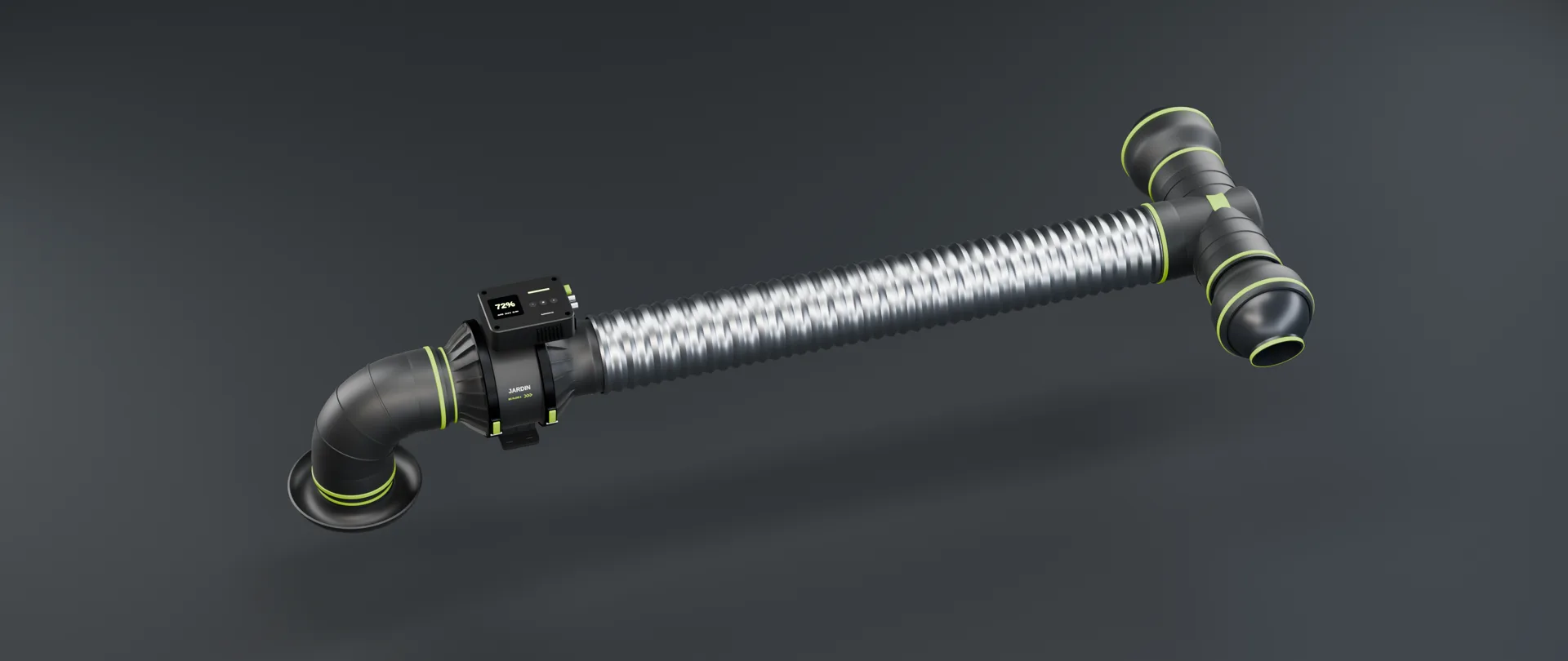
Circulation without a fan in the canopy
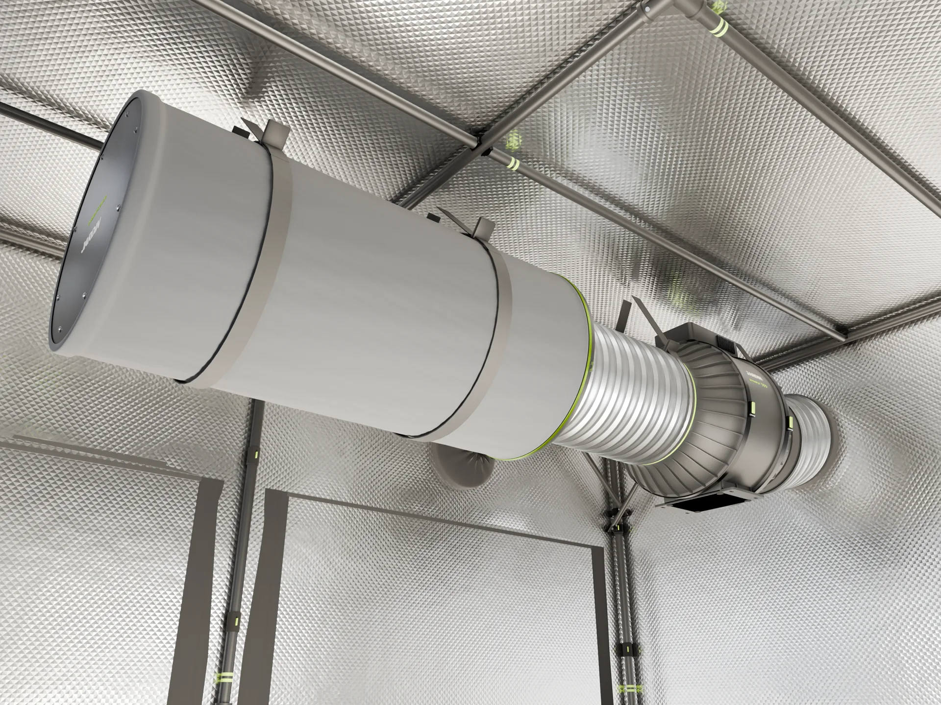
Hang one EC Flow out of the grow space and draw at one corner. At the far end of the run a Flow Tee splits it to two aimable Flow Jets, throwing opposite ways across the canopy: directed air, no fan in the plants and no growing room taken. Try it in the tent above.
05
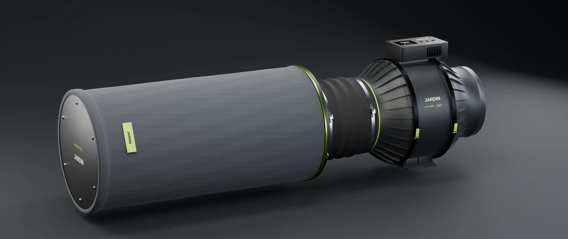
Fan to filter on one axis
EC Flow 8, a Flex Coupler and Carbon Flow 8 in line. The duct size is the only thing you choose.
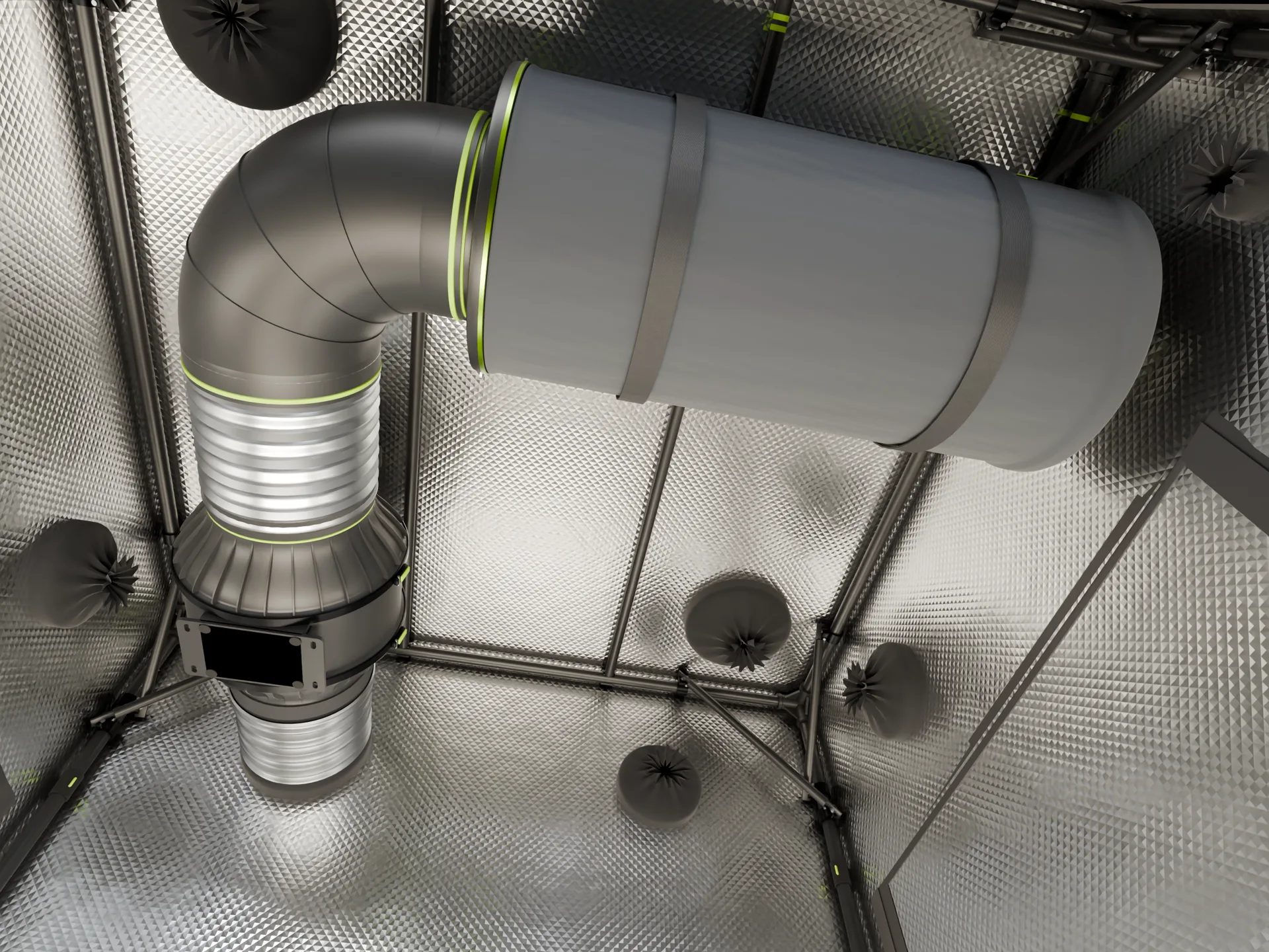
06
Hangs in a Jardin tent
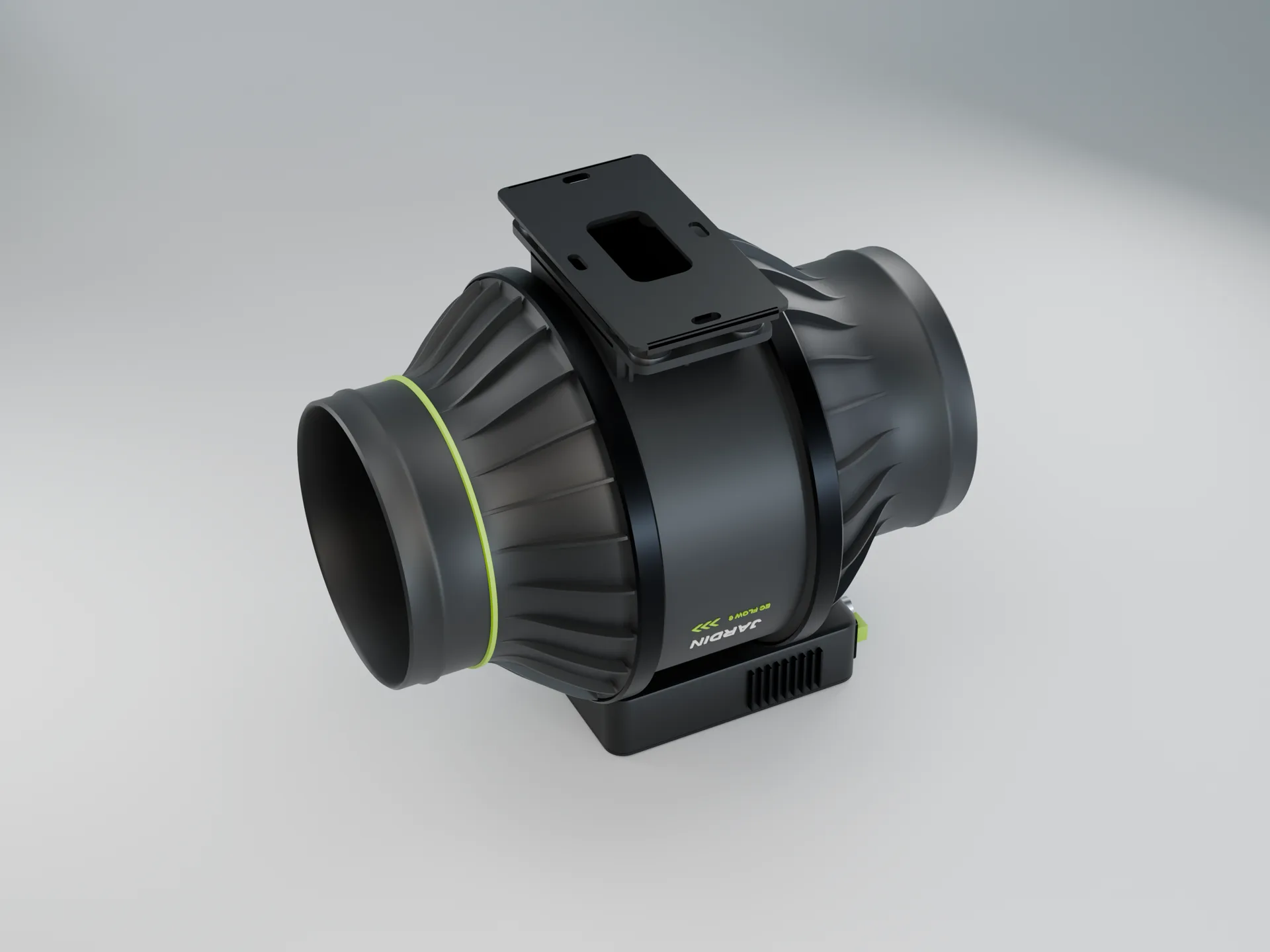
Roof straps, the tent's own exhaust port and the controller cable out through the service column.
Gallery · tap for full size
Look closer.
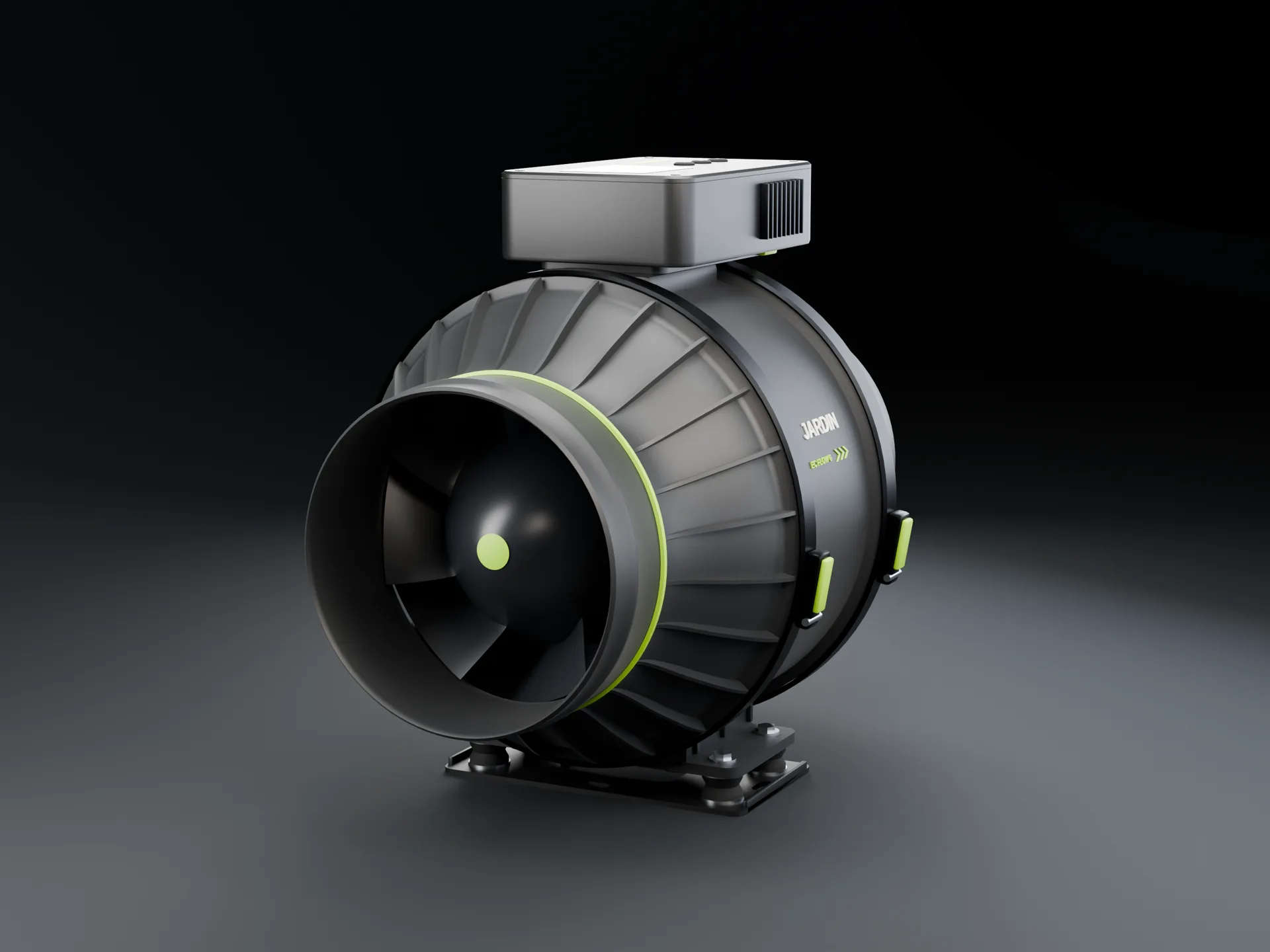
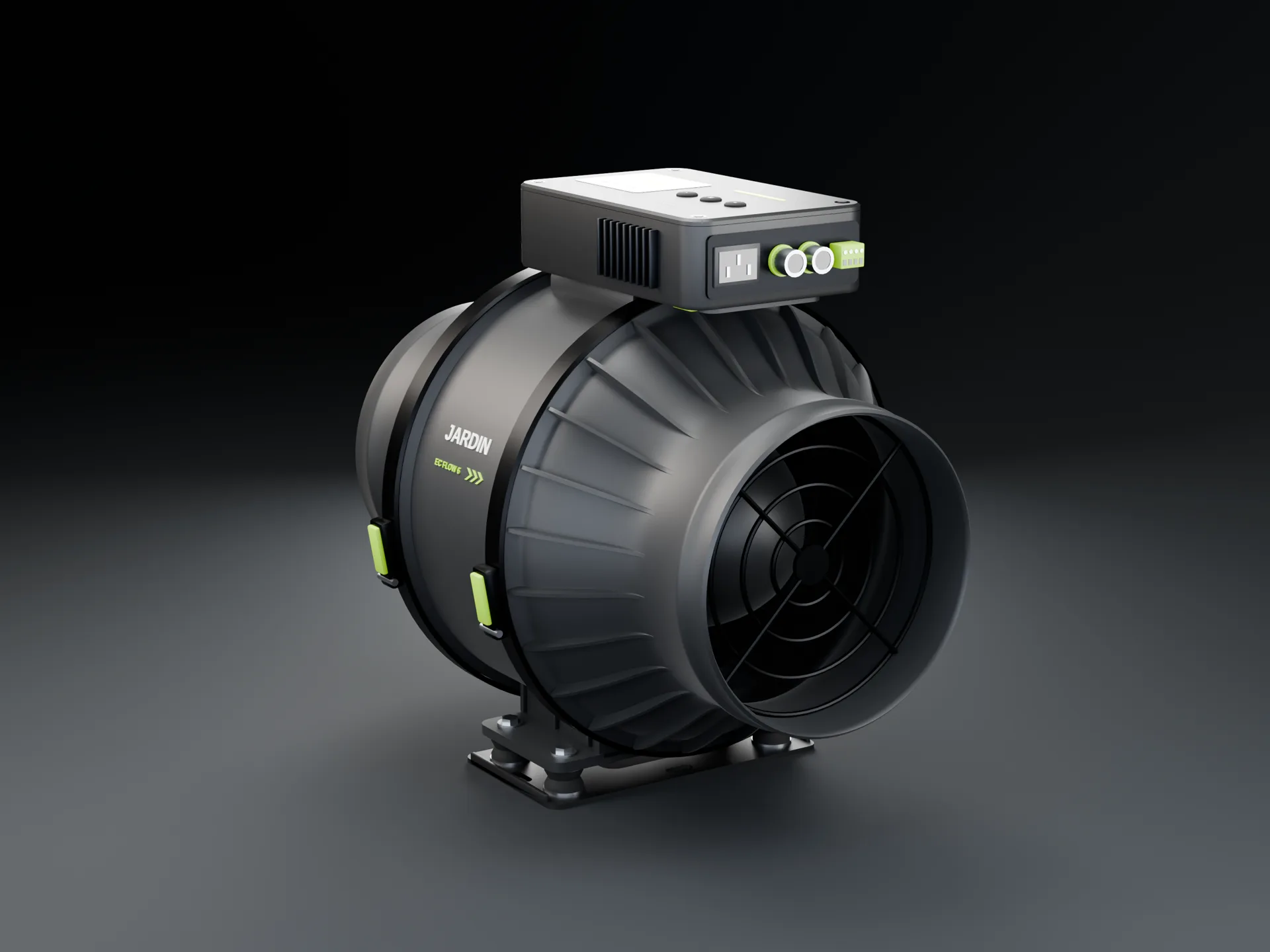
Every render whole, at its own shape. Concept art from the design files, not product photos.
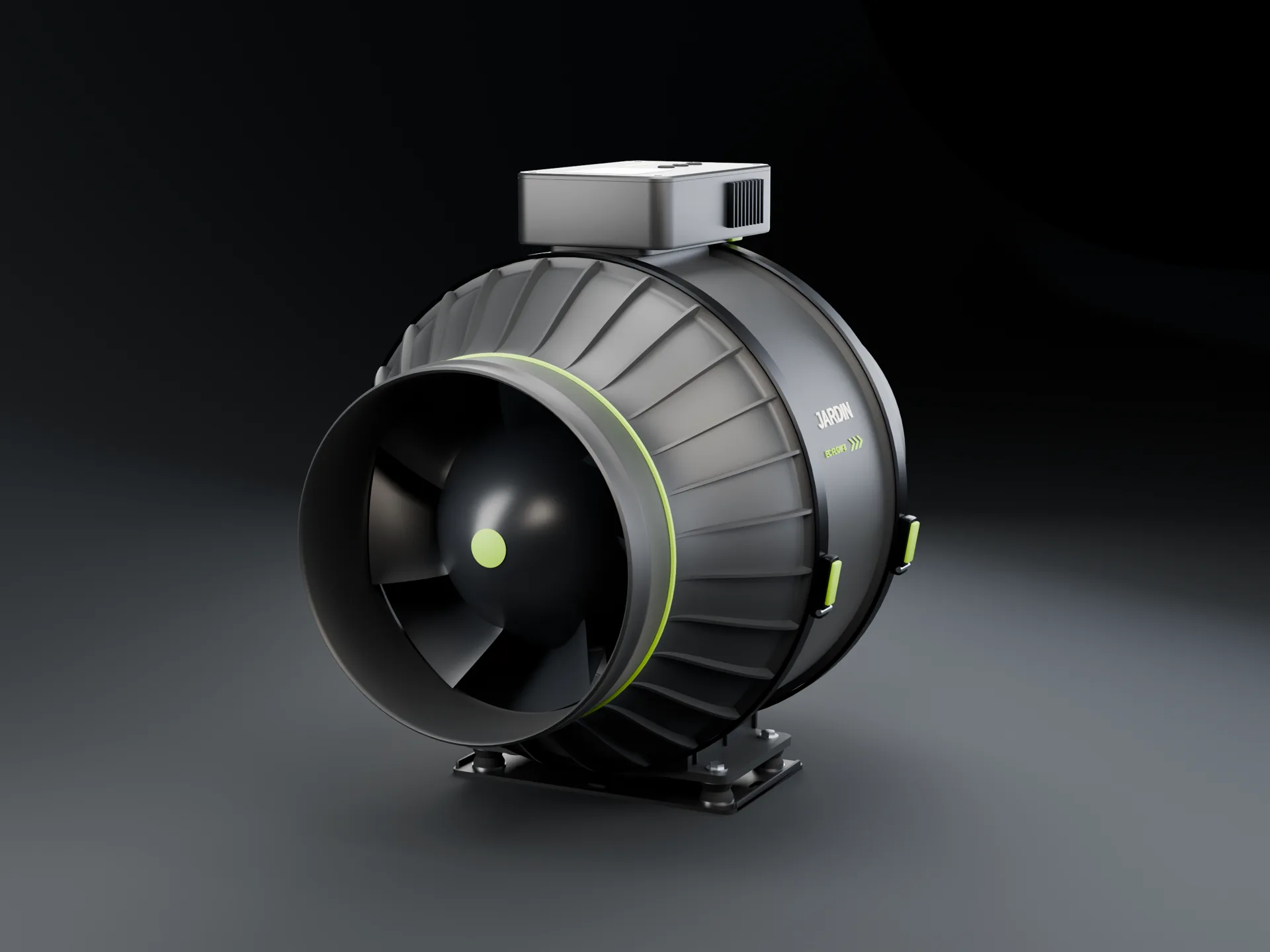
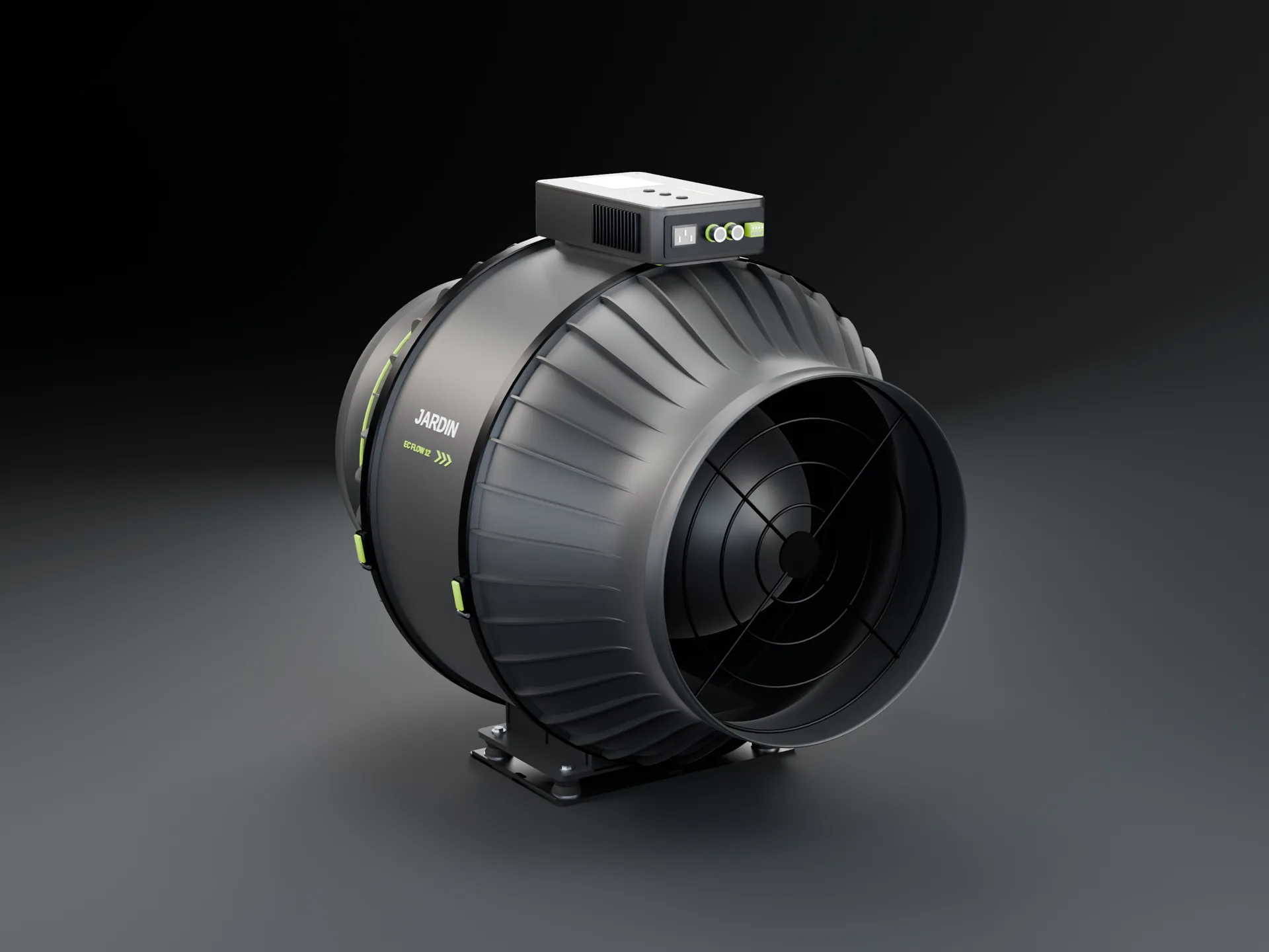
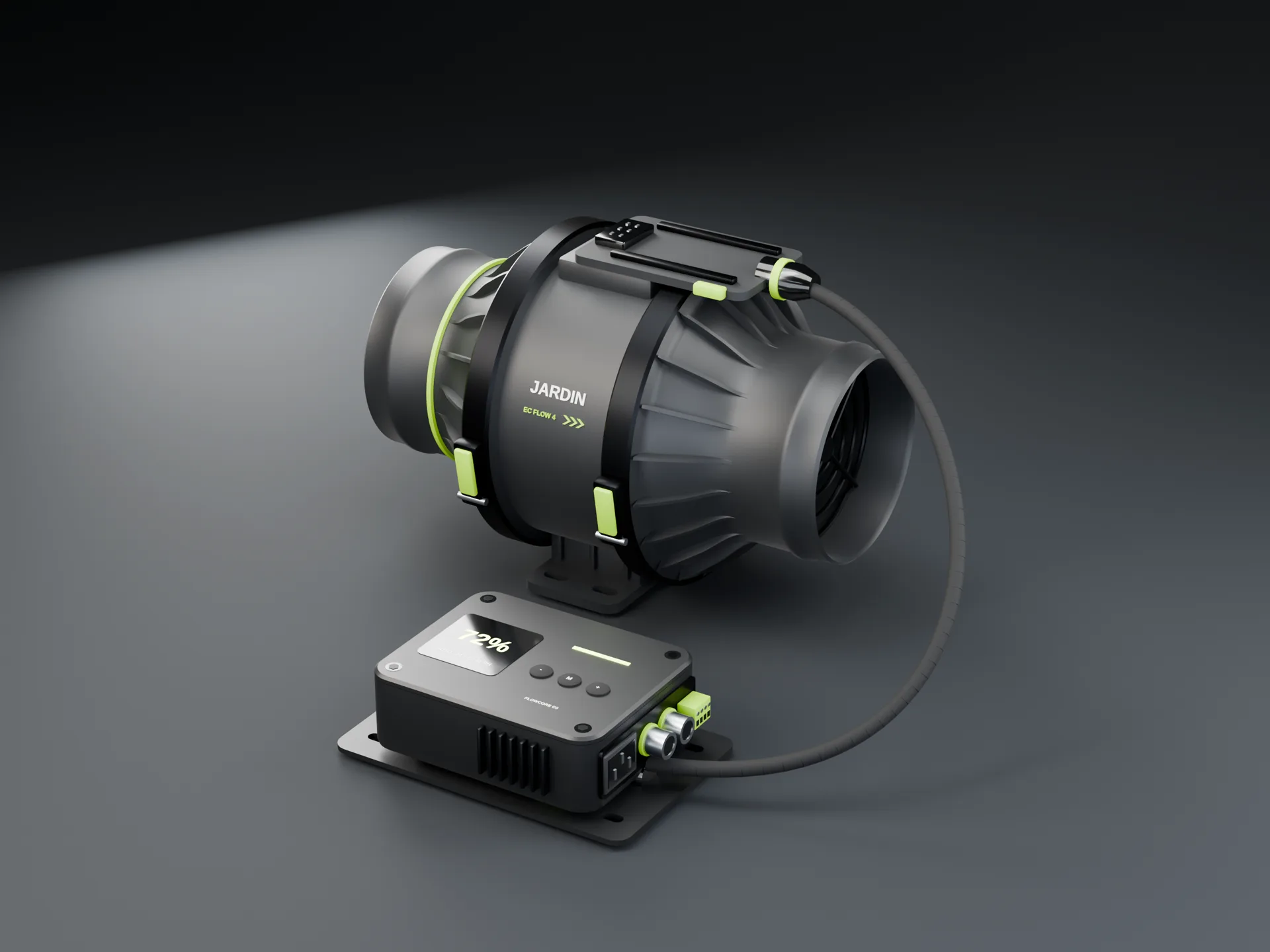
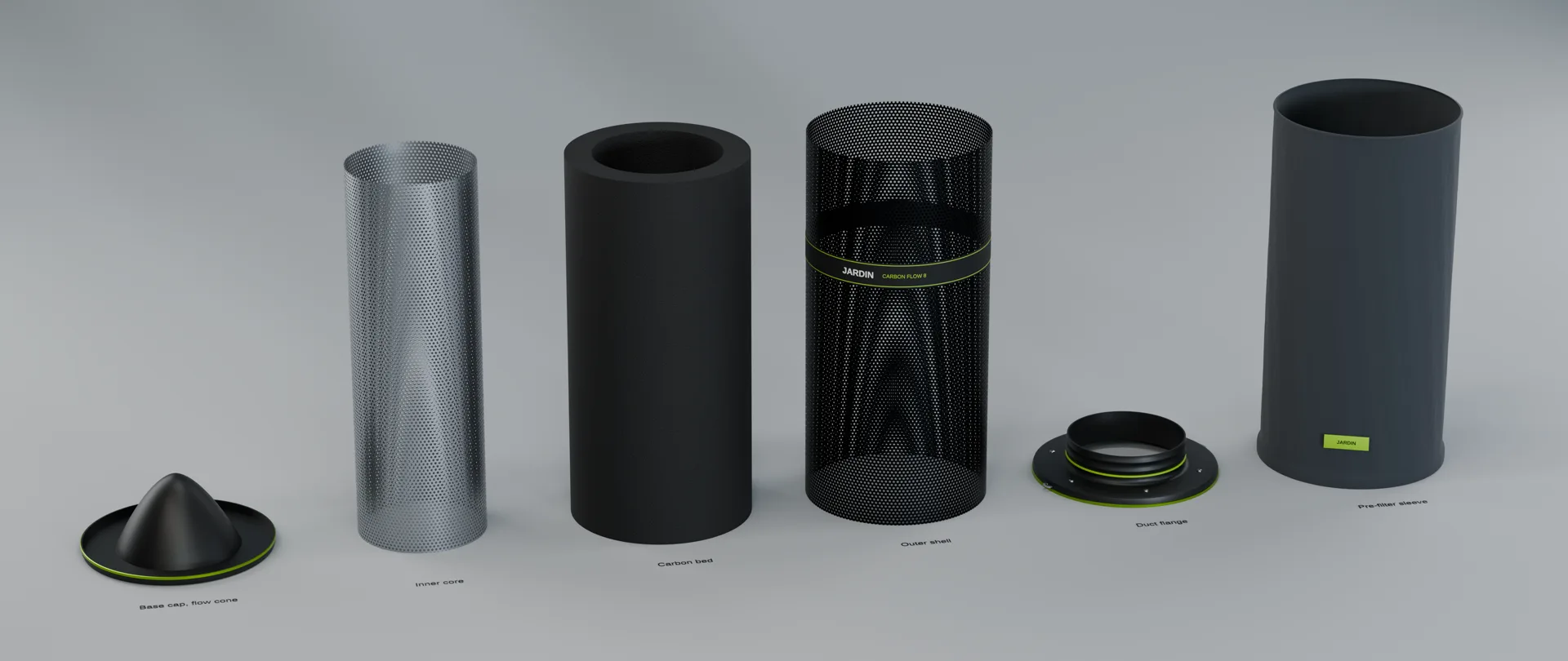
Specs · design targets Designed
The numbers, labelled for what they are.
Every figure is a design target from the drawings. The real deliverable is an airflow-against-pressure curve at 0, 25, 50, 100, 150 and 200 Pa, with input power at each point, measured on a sample.
| Model | Duct | L × W × H on mount, mm | Blades / vanes | Motor | Controller | Free-air target, CFM |
|---|---|---|---|---|---|---|
| EC Flow 4 | 100 mm | 244 × 157 × 212 | 7 / 11 | M100 | FlowCore C0 | 150–220 |
| EC Flow 6 | 150 mm | 316 × 225 × 284 | 7 / 11 | M150 | FlowCore C1 | 350–500 |
| EC Flow 8 | 200 mm | 387 × 293 × 352 | 7 / 11 | M200 | FlowCore C1 | 600–850 |
| EC Flow 10 | 250 mm | 458 × 362 × 430 | 9 / 13 | M250 | FlowCore C2 | 900–1,250 |
| EC Flow 12 | 300 mm | 529 × 430 × 498 | 9 / 13 | M300 | FlowCore C2 | 1,300–1,800 |
What's done
- Fully engineered. Every fan, filter, Breeze and flow part drawn and specified, down to its material and how it's made, and every render checked against the parts list.
- Labelled from the model. The part labels on this page come out of the same 3D scene.
What the money buys
- Moulds and the motor run. Housing and impeller tooling, the stator and rotor, the controller board.
- Testing and listing. Fan curves, noise and heat on a rig, and the safety listing for the controller.
- A first production run for reservations, if the EC Flow goal and its reservation count are met. If not, every deposit comes back.
Founding Members · first in line
Help take EC Flow from drawings to your roof.
Reserve on Fund the Bay with a refundable deposit, or join the waitlist to follow the build.